A stacker with high carrying capacity and its transportation method

A technology of high load-carrying capacity and stacker, which is applied in the direction of transportation, packaging, storage devices, etc., can solve the problems of low service life and easy damage, and achieve the effect of improving load capacity

Inactive Publication Date: 2021-06-11
JINKEN COLLEGE OF TECH
View PDF9 Cites 0 Cited by
  • Summary
  • Abstract
  • Description
  • Claims
  • Application Information

AI Technical Summary

Problems solved by technology

[0004] Then, one common point of transmission methods such as the chain sprocket assembly and the pulley assembly is that only the active force can be applied to one side of the column and the telescopic fork of the stacker, while the other side of the column and the telescopic fork is subjected to passive force. Sliding, but when doing linear motion, the column and the telescopic fork will deviate to the passive sliding side under the action of one side of the force, which is prone to damage, especially when the passive sliding side is loaded with heavy loads. Rigid friction caused by shifting, leading to the problem of low service life

Method used


Image

  • A stacker with high carrying capacity and its transportation method
  • A stacker with high carrying capacity and its transportation method
  • A stacker with high carrying capacity and its transportation method

Examples


Embodiment Construction

[0037] In the following description, numerous specific details are given in order to provide a more thorough understanding of the present invention. It will be apparent, however, to one skilled in the art that the present invention may be practiced without one or more of these details. In other examples, some technical features known in the art are not described in order to avoid confusion with the present invention.

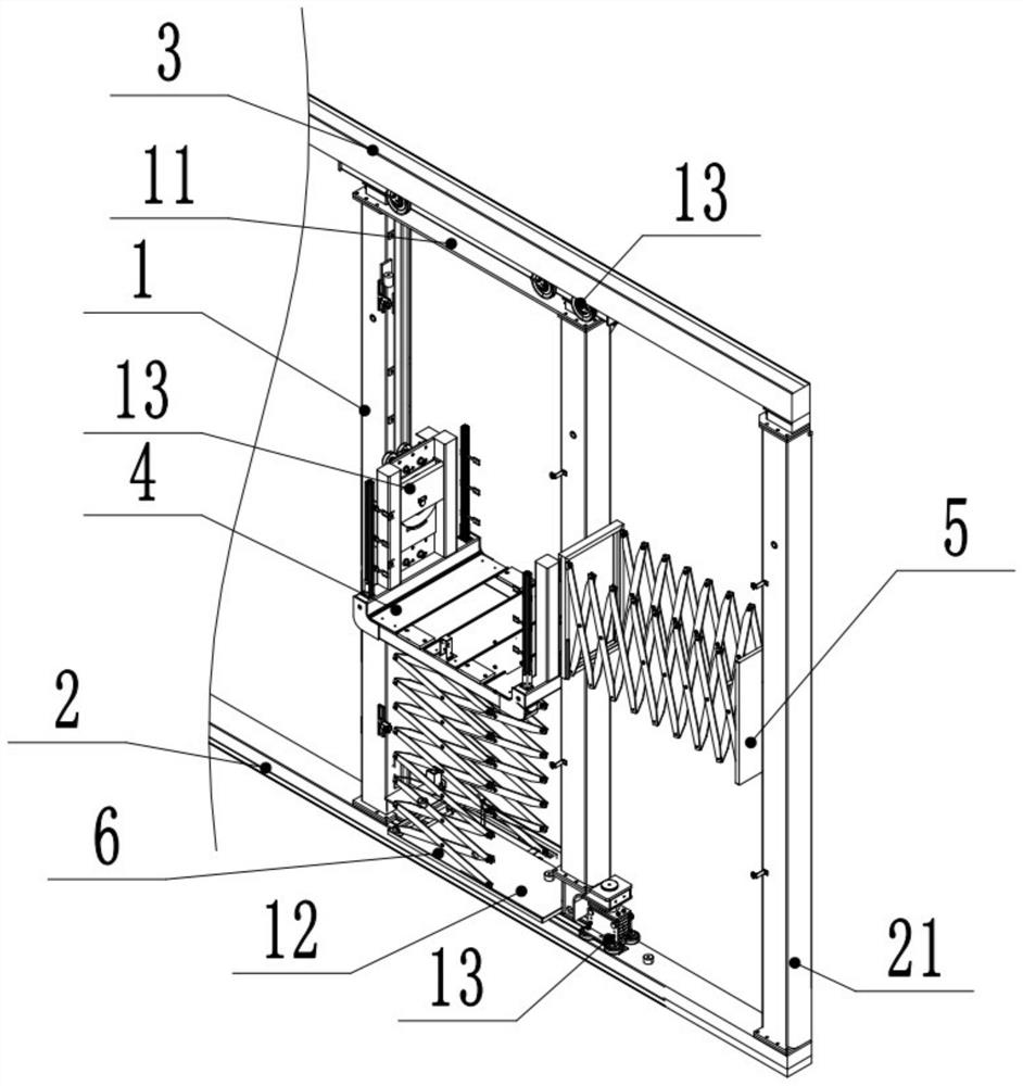
[0038] The applicant found that there are two problems in the transportation of heavy loads in the existing stackers that use flexible connections such as chain sprocket assemblies and pulley assemblies for transmission. One is that the small bearing capacity of the chains and belts limits the stacking The load capacity of the stacker, the other is to use chains and belts to apply tension to one side of the stacker's column and telescopic fork, and the other side to slide passively, and the direction of force on the side where the active force and passive slidin...


PUM


Abstract

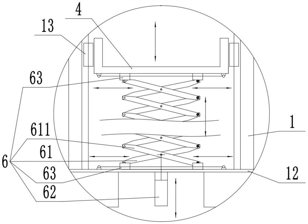
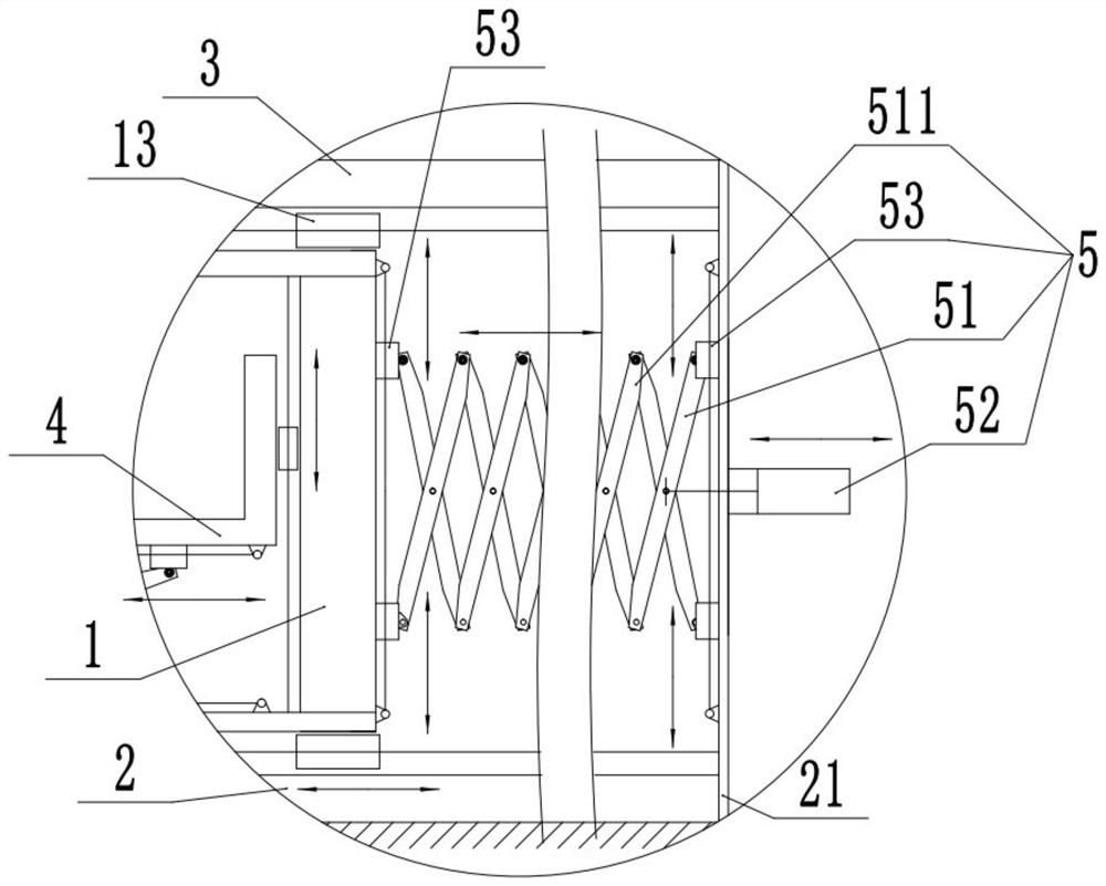
The invention discloses a stacker with high load-bearing capacity and a transportation method, belonging to the field of storage equipment. The stacker with high load-bearing capacity includes: a column, a lower rail, an upper rail, a telescopic fork, a transverse power assembly and a vertical Orientation power assembly, at least one column, the column moves horizontally in a straight line between the lower rail and the upper rail, the telescopic fork makes a vertical linear motion on one side of the column, and the middle position between one end of the horizontal power assembly and the other side of the column Fixed connection, the horizontal power assembly and the telescopic fork are respectively located on both sides of the column, one end of the horizontal power assembly is fixedly connected to the middle position of the bottom end of the telescopic fork, and both the horizontal power assembly and the vertical power assembly are rigidly driven; the present invention, through The horizontal power assembly and the vertical power assembly are rigidly driven in the middle of the column and the telescopic fork, so that the stacker can carry out high-load heavy load transportation, and reduces the probability of deviation during the work process, improving the use of life.

Description

technical field [0001] The invention relates to the field of storage equipment, in particular to a high-carrying-capacity stacker and a transportation method. Background technique [0002] As the basic equipment of the automatic three-dimensional warehouse, the stacker performs the work of transporting, entering and exiting the goods, but the existing stackers all use the flexible connection of the chain sprocket assembly and the pulley assembly to realize the stacker. Long-distance linear motion. [0003] Firstly, chains, sprocket assemblies and pulley assemblies, which are flexibly connected chains and belts, have a small bearing capacity and are not suitable for heavy-duty transportation with high loads. [0004] Then, one common point of transmission methods such as the chain sprocket assembly and the pulley assembly is that only the active force can be applied to one side of the column and the telescopic fork of the stacker, while the other side of the column and the t...

Claims


Application Information

Patent Timeline
Patent Type & Authority Patents(China)
IPC IPC(8): B65G1/04
CPCB65G1/0407
Inventor 陶俊
Owner JINKEN COLLEGE OF TECH
Why Eureka
Try Eureka