Polishing device provided with fixing structure and used for wrench machining

A technology for fixing structures and tools, which is applied in the direction of manufacturing tools, metal processing equipment, grinding machines, etc. It can solve the problems of inconvenient and quick fixing and installation of wrenches, inability to adjust the level and height of grinding tools, and poor grinding performance, so as to reduce rigid impact , Maintain stability, simple and convenient operation

Inactive Publication Date: 2020-03-06
东莞市史雷帝三维数控科技有限公司
View PDF0 Cites 0 Cited by
  • Summary
  • Abstract
  • Description
  • Claims
  • Application Information

AI Technical Summary

Problems solved by technology

[0004] Aiming at the deficiencies of the prior art, the present invention provides a grinding device with a fixed structure for wrench processing, which solves the problem that the grinding equipment proposed in the above background technology has a relatively simple internal and external structure and poor grinding performance during use. The fixed installation ability of the wrench is not convenient and quick enough, and the equipment cannot adjust the level of the grinding tool according to the size of the wrench when it is in use, which cannot meet people's needs and other problems.

Method used


Image

  • Polishing device provided with fixing structure and used for wrench machining
  • Polishing device provided with fixing structure and used for wrench machining
  • Polishing device provided with fixing structure and used for wrench machining

Examples


Embodiment Construction

[0028] The following will clearly and completely describe the technical solutions in the embodiments of the present invention with reference to the accompanying drawings in the embodiments of the present invention. Obviously, the described embodiments are only some, not all, embodiments of the present invention.

[0029] In the description of the present invention, unless otherwise stated, the meaning of "plurality" is two or more; the terms "upper", "lower", "left", "right", "inner", "outer" , "front end", "rear end", "head", "tail", etc. indicate the orientation or positional relationship based on the orientation or positional relationship shown in the drawings, and are only for the convenience of describing the present invention and simplifying the description, rather than Indicates or implies that the device or element referred to must have a particular orientation, be constructed and operate in a particular orientation, and therefore should not be construed as limiting the...


PUM


Abstract

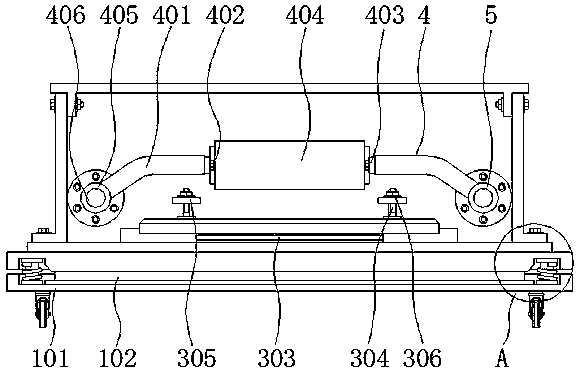
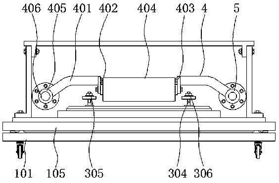
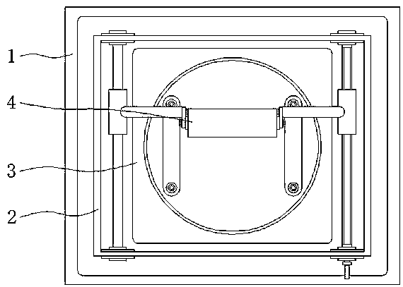
The invention discloses a polishing device provided with a fixing structure and used for wrench machining and relates to the technical field of wrench machining equipment, in particular to a polishingdevice provided with the fixing structure and used for wrench machining. The polishing device comprises a supporting mechanism and a polishing mechanism. An outer frame is arranged above the supporting mechanism. The polishing mechanism is arranged above a positioning installation mechanism. The polishing mechanism comprises supporting bending rods, positioning screws, control arms, a steel brushsleeve, positioning sleeves and guide pillars. The supporting bending rods are arranged on the right sides of the positioning sleeves. The control arms are arranged at the rear ends of the positioning screws. By means of the polishing device provided with the fixing structure and used for wrench machining, the structure is increased, meanwhile, the use performance of the whole device is greatly improved, when the improved equipment is used, a wrench clamping manner is simpler and more convenient, in addition, adjusting operation can be conducted on the polishing height through the device according to different specifications of wrenches, the equipment application face is indirectly enlarged, and the use requirements of people are effectively met.

Description

technical field [0001] The invention relates to the technical field of wrench processing equipment, in particular to a grinding device with a fixed structure for wrench processing. Background technique [0002] A wrench is a commonly used installation and disassembly tool. It uses the principle of leverage to twist bolts, screws, nuts and other hand tools that hold the openings or sockets of the bolts or nuts. The wrench is usually made at one or both ends of the handle. There is an external force applied to the handle by the handle, and the bolt or nut can be twisted by applying an external force to the opening or sleeve of the bolt or nut. When using, an external force is applied to the handle along the thread rotation direction to twist the bolt or nut. The production process requires grinding of the external surface, and grinding is a kind of surface modification technology. It generally refers to a processing method that uses rough objects to change the physical propert...

Claims


Application Information

Patent Timeline
Patent Type & Authority Applications(China)
IPC IPC(8): B24B27/00B24B41/06B24B41/02B24B41/00
CPCB24B27/00B24B27/0092B24B41/00B24B41/02B24B41/06
Inventor 黄红梅马浩鹏
Owner 东莞市史雷帝三维数控科技有限公司
Why Eureka
Try Eureka