Electric arc spraying device for machining

An arc spraying and mechanical processing technology, applied in coating, fusion spraying, metal material coating technology and other directions, can solve the problems of easy falling off of the coating, affecting the effect of spraying, etc., to achieve fast gas flow, improve efficiency, prevent The effect of dust accumulation

Inactive Publication Date: 2020-02-14
何洋洋
View PDF7 Cites 3 Cited by
  • Summary
  • Abstract
  • Description
  • Claims
  • Application Information

AI Technical Summary

Problems solved by technology

Before arc spraying, the workpiece needs to be preheated so that the metal particles can be more tightly attached to the surface of the workpiece, but in the actual processing process, it is necessary to send batches of preheated workpieces to the spraying workshop for further processing. Spraying, due to the large number of sprayed workpieces, the temperature of the workpieces that are not sprayed in time after preheating will gradually decrease, which will affect the spraying effect and cause the coating to fall off easily

Method used


Image

  • Electric arc spraying device for machining
  • Electric arc spraying device for machining
  • Electric arc spraying device for machining

Examples


Embodiment 1

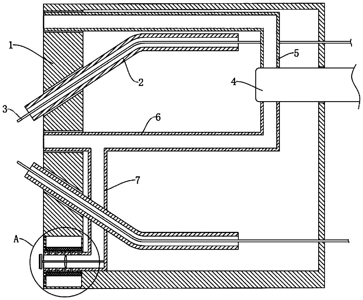
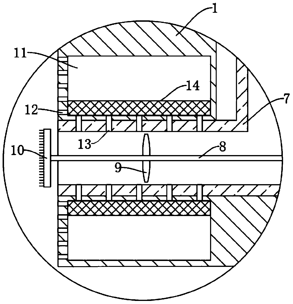
[0022] refer to Figure 1-2 , an arc spraying device for mechanical processing, comprising a spray gun body 1, two conductive tips 2 are installed in the spray gun body 1, a metal wire 3 is arranged in the conductive tip 2, a vortex tube 4 is embedded in the spray gun body 1, and the vortex tube The upper and lower sides of 4 are respectively equipped with cold air pipe 5 and hot air pipe 6, and the outlet end of hot air pipe 6 is located between two metal wires 3, and the lower end of hot air pipe 6 is fixedly connected with a conduit 7 communicating with the inside thereof, and the end of conduit 7 A rotating shaft 8 is rotatably connected to the inner wall, and a plurality of axial flow fan blades 9 are fixedly connected to the side wall of the rotating shaft 8. The end of the rotating shaft 8 far away from the conduit 7 is fixedly connected to a brush plate 10, and the side of the brush plate 10 away from the spray gun body 1 is provided Has multiple bristles.

[0023] It...

Embodiment 2

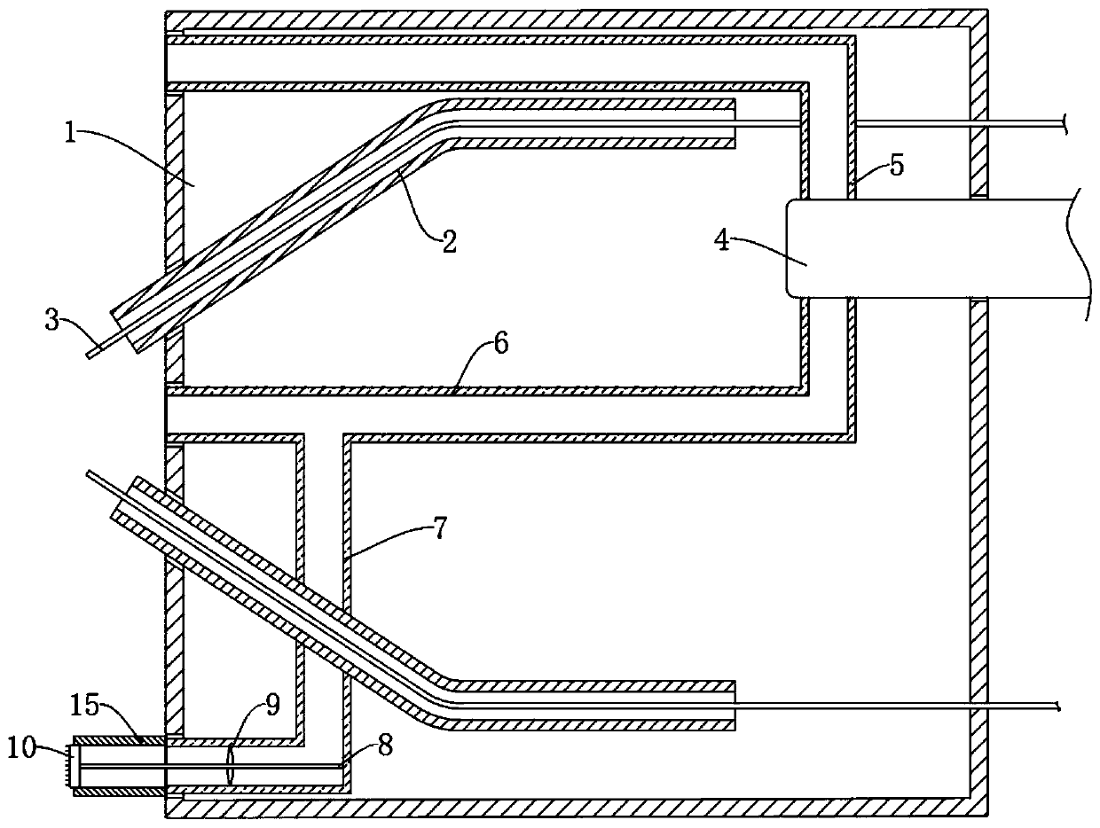
[0032] refer to image 3 , different from Embodiment 1, the side wall of the spray gun body 1 is fixedly connected with a glass sleeve 11, the glass sleeve 11 is made of high temperature resistant material, and the upper and lower ends of the brush plate 10 are in contact with the inner wall of the glass sleeve 11 Frictional contact, the surface of the brush plate is coated with high temperature and wear-resistant materials, and in this embodiment, there is no need to set the square cavity 11, the through hole 12, the negative pressure hole 13 and the filter screen 14. The surface coating of the brush plate 10 can be made of high-temperature wear-resistant material for boiler pipes, which is a variety of high-temperature-resistant and wear-resistant inorganic non-metallic materials that are close to the expansion coefficient of steel. Celsius, and can generate static electricity in the process of continuous friction with the inner wall of the glass sleeve 11 .

[0033] In thi...


PUM


Abstract

The invention discloses an electric arc spraying device for machining. The electric arc spraying device comprises a spray gun body, wherein two contact tubes are mounted in the spray gun body, metal wires are arranged in the contact tubes, a vortex tube is embedded in the spray gun body, a cold air tube and a hot air tube are mounted on the upper side and the lower side of the vortex tube respectively, besides, the air outlet end of the hot air tube is located between the two metal wires, a guide tube communicating with inside of the hot air tube is fixedly connected with the lower end of thehot air tube, a rotating shaft is rotationally connected onto an inner wall of the guide tube, and multiple axial flow blades are fixedly connected with a side wall of the rotating shaft. When the spray gun performs spraying from top to bottom, the guide tube located at the lower part can guide out hot air flow, a to-be-sprayed surface of a workpiece can be subjected to preheating and warming treatment in advance, the condition that the spraying effect is affected due to temperature reduction of the workpiece in a process of waiting for spraying can be effectively prevented, a coating formed after spraying can be rapidly cooled by the cold air tube located at the upper part, and the spraying efficiency is increased.

Description

technical field [0001] The invention relates to the technical field of machining equipment, in particular to an arc spraying device for machining. Background technique [0002] During the mechanical processing of the workpiece, it is often necessary to spray paint on the surface of the workpiece to create a special working surface, so that the workpiece can achieve: anti-corrosion, wear-resistant, anti-friction, high temperature resistance, anti-oxidation, heat insulation, insulation, conductivity, anti-microwave Radiation and many other functions. Existing spraying techniques include flame spraying, explosive spraying, supersonic spraying, arc spraying, plasma spraying, and laser spraying. [0003] Among them, arc spraying uses the arc generated between two continuously fed metal wires as a heat source to melt the metal, atomizes the molten metal with compressed air, and accelerates the atomized metal droplets to spray them on the workpiece to form a coating. Floor. Befo...

Claims


Application Information

Patent Timeline
Patent Type & Authority Applications(China)
IPC IPC(8): C23C4/131C23C4/06
CPCC23C4/06C23C4/131
Inventor 何洋洋
Owner 何洋洋
Why Eureka
Try Eureka