
Heat exchanger arrangement structure of pre-concentration tower

A technology for arranging structures and heat exchangers, applied to indirect heat exchangers, lighting and heating equipment, etc., can solve problems such as volatilization, low concentration efficiency, and high temperature of liquid medium

Pending Publication Date: 2020-02-14
CSSC SHENGHUI EQUIP
View PDF0 Cites 0 Cited by
  • Summary
  • Abstract
  • Description
  • Claims
  • Application Information

AI Technical Summary

Problems solved by technology

[0002] After the production of the liquid medium, some gas will remain inside. In order to increase the concentration of the liquid medium, the residual gas needs to be discharged, so a pre-concentration tower is required to discharge the residual gas, and then follow-up operations are performed; the existing pre-concentration The tower passes the liquid medium through a whole row of heat exchangers and then heats the liquid medium passing through the liquid accumulation tank to accelerate the separation of gas and liquid. In actual use, a long row of heat exchangers needs to be arranged to ensure that the liquid medium and heat exchanger In the actual heating process, the temperature of the liquid medium is often too high due to heating, resulting in unnecessary volatilization in the follow-up, which makes the concentration efficiency low

Method used


Image

  • Heat exchanger arrangement structure of pre-concentration tower

Examples


specific Embodiment

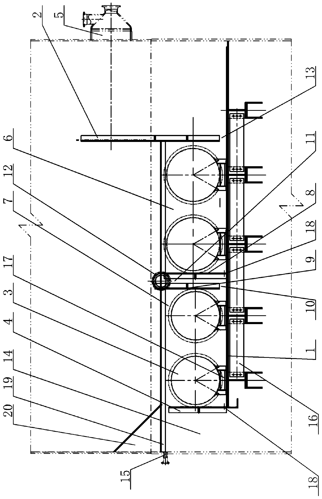
[0018] In a specific embodiment, four heat exchangers 3 are arranged in the region of the corresponding bottom transverse plate 1 from the first longitudinal partition plate 2 to the third longitudinal partition plate 4 , and two heat exchangers 3 are arranged in the first heat exchange cavity 6 . There are two heat exchangers 3, two heat exchangers 3 are arranged in the second heat exchange cavity 7, and each heat exchanger 3 is supported by the bracket 17 at the corresponding position of the bottom horizontal plate 1;

[0019] Small-diameter drain holes 18 are provided at the bottoms of the first upper limit partition plate 8 and the third longitudinal partition plate 4 to ensure that the liquid is drained when no subsequent work is performed;

[0020] It also includes an auxiliary horizontal connecting bar 19, one end of the auxiliary horizontal connecting bar 19 is fixed to the middle area in the height direction of the first longitudinal partition 2, the other end is conne...


PUM


Abstract

The invention provides a heat exchanger arrangement structure of a pre-concentration tower. By means of the heat exchanger arrangement structure, arrangement of heat exchangers is reliable and effective, and it is ensured that gas-liquid separation is efficient. The heat exchanger arrangement structure comprises a bottom transverse plate, a first longitudinal partition plate, the multiple heat exchangers, a second partition longitudinal plate assembly and a third longitudinal partition plate. One end of the bottom transverse plate extends to the corresponding position below a liquid inlet. Thefirst longitudinal partition plate blocks the corresponding height position of the liquid inlet. A third longitudinal partition plate protruding upwards is arranged at the other end of the bottom transverse plate. The multiple heat exchangers are arranged in the area, corresponding to the space between the first longitudinal partition plate and the third longitudinal partition plate, of the bottom transverse plate. The multiple heat exchangers are divided by the second partition longitudinal plate assembly to form two independent heat exchange cavities specifically including the first heat exchange cavity and the second heat exchange cavity. The second partition longitudinal plate assembly specifically comprises a first upper limiting partition plate and a second lower limiting partitionplate. The bottom of the first upper limiting partition plate is fixedly connected to the bottom transverse plate.

Description

technical field [0001] The invention relates to the technical field of liquid concentration equipment, in particular to a heat exchanger arrangement structure of a pre-concentration tower. Background technique [0002] After the production of the liquid medium, there will be some gas remaining in it. In order to increase the concentration of the liquid medium, the residual gas needs to be discharged. Therefore, a pre-concentration tower is required to discharge the residual gas, and then follow-up operations are carried out; the existing pre-concentration After passing the liquid medium through a whole row of heat exchangers, the tower will heat the liquid medium passing through the liquid accumulation tank to accelerate the gas-liquid separation. In actual use, a longer row of heat exchangers needs to be arranged to ensure the liquid medium and heat exchanger. In the actual heating process, the temperature of the liquid medium is often too high, resulting in unnecessary vol...

Claims


Application Information

Patent Timeline
IPC IPC(8): F28D21/00
CPCF28D21/00F28D2021/0019
Inventor 郑美娟肖霞朱国荣
Owner CSSC SHENGHUI EQUIP
Learn More