MOSFET current detection circuit and method
A current detection circuit and current detection technology, applied in the direction of measuring current/voltage, measuring device, measuring electrical variables, etc., can solve the problems of large temperature influence and low detection accuracy, and achieve good temperature characteristics, high detection accuracy, and elimination of influence. Effect
- Summary
- Abstract
- Description
- Claims
- Application Information
AI Technical Summary
Problems solved by technology
Method used
Image


Examples
Embodiment 1
[0026] Embodiment 1: as figure 1 As shown, a MOSFET current detection circuit includes a power switch tube Q4, a detection switch tube Q3, a thermistor R3, a fixed value resistor R2, and a voltage detection circuit; the power switch tube Q4 is switched synchronously with the detection switch tube Q3 , when the power switch tube Q4 is turned on, the detection circuit voltage corresponds to the voltage of the DS terminal of the power switch tube Q4, and then the current of the power switch tube Q4 is obtained.
[0027] The power switching tube Q4 to be detected is mirror-connected to the detection switching tube Q3, the thermistor R3 and the fixed value resistor R2 are connected in series with the detection switching tube Q3, and the thermistor R3 is connected to the detection switching tube Q3 The resistance changes correspondingly with the change of temperature, which compensates the temperature characteristic of the on-resistance of the switching tube Q3 to be detected.
[0...
Embodiment 2
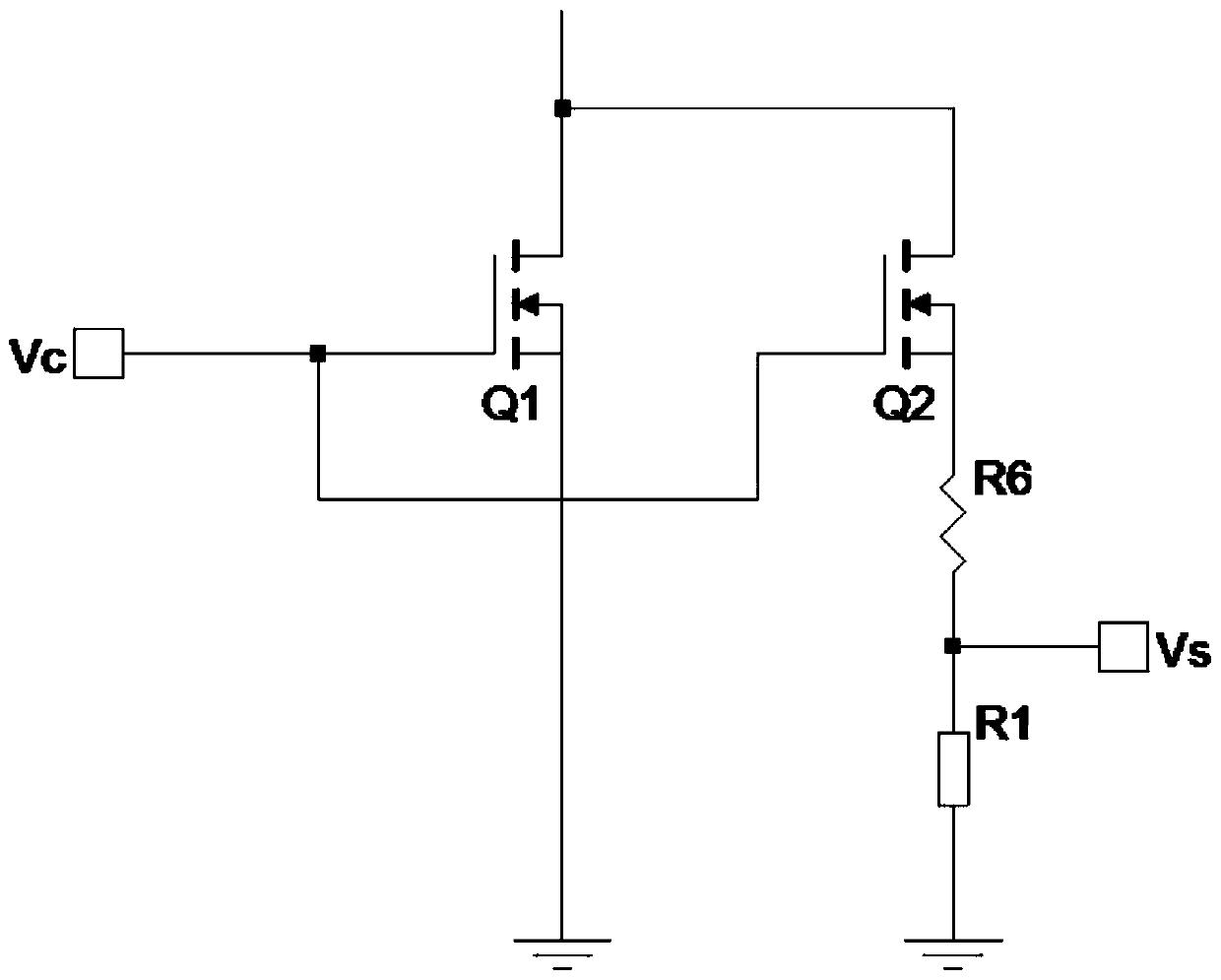
[0032] Embodiment 2: as figure 2 As shown, a MOSFET current detection circuit includes a power switch tube Q1, a detection switch tube Q2, a thermistor R6, a fixed value resistor R1, and a voltage detection circuit; the power switch tube Q1 and the detection switch tube Q2 switch synchronously , when the power switch tube Q1 is turned on, the detection circuit voltage corresponds to the voltage of the DS terminal of the power switch tube Q1, and then the current of the power switch tube Q1 is obtained.
[0033] The power switching tube Q1 to be detected is mirror-connected to the detection switching tube Q2, the thermistor R6 and the fixed value resistor R1 are connected in series with the detection switching tube Q2, and the thermistor R6 is connected to the detection switching tube Q2 The resistance changes correspondingly with the change of temperature, which compensates the temperature characteristic of the on-resistance of the switching tube Q2 to be detected.
[0034] ...
Embodiment 3
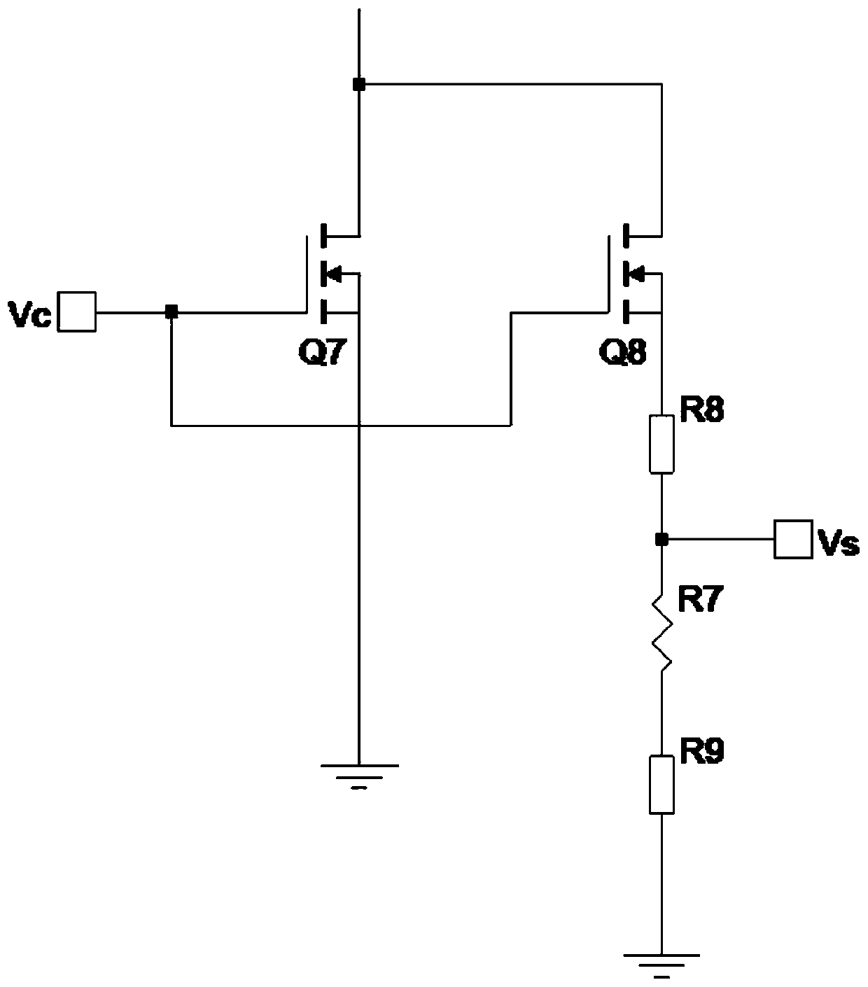
[0038] Embodiment 3: as image 3 As shown, a MOSFET current detection circuit includes a power switch tube Q7, a detection switch tube Q8, a thermistor R7, a fixed value resistor R8 and a voltage detection circuit; the power switch tube Q7 is switched synchronously with the detection switch tube Q8 , when the power switch tube Q7 is turned on, the detection circuit voltage corresponds to the voltage of the DS terminal of the power switch tube Q7, and then the current of the power switch tube Q7 is obtained.
[0039] The to-be-detected power switch tube Q7 is mirror-connected to the detection switch tube Q8, the thermistor R7 and the fixed value resistor R8 are connected in series with the detection switch tube Q8, and the thermistor R7 and the to-be-detected switch tube Q8 conduct The resistance changes correspondingly with the change of temperature, which compensates the temperature characteristic of the on-resistance of the switching tube Q8 to be detected.
[0040] It also...
PUM
 Abstract
Description
Claims
Application Information
 - R&D
- Intellectual Property
- Life Sciences
- Materials
- Tech Scout
- Unparalleled Data Quality
- Higher Quality Content
- 60% Fewer Hallucinations
Browse by: Latest US Patents, China's latest patents, Technical Efficacy Thesaurus, Application Domain, Technology Topic, Popular Technical Reports.
© 2025 PatSnap. All rights reserved.Legal|Privacy policy|Modern Slavery Act Transparency Statement|Sitemap|About US| Contact US: help@patsnap.com