Electromagnetic relay

An electromagnetic relay and electrical connection technology, applied in electromagnetic relays, electromagnetic relay details, relays, etc., can solve the problems of complex injection molding process, high preparation cost, relay failure, etc., to simplify the injection molding process, improve the heat dissipation effect, and prolong the use. effect of life

Pending Publication Date: 2020-02-14
XIAMEN HONGFA AUTOMOTIVE ELECTRONICS CO LTD
View PDF0 Cites 5 Cited by
  • Summary
  • Abstract
  • Description
  • Claims
  • Application Information

AI Technical Summary

Problems solved by technology

But the main body of the static reed and the base are injection-molded into one, and its existing problems are: 1. The heat dissipation of the static reed is poor, which affects the performance of the relay; especially for high-current electromagnetic relays (such as relays with a contact current of 200A and above ), calorific value Q=I 2 *R*t, the calorific value is proportional to the square value of the current. The calorific value of a high-current relay is very large. If it cannot be effectively and quickly dissipated heat, the relay is very likely to fail due to high temperature; 2. The injection molding process is complicated and the defective rate Higher, higher preparation cost; 3. The contact turnover of the static reed is sent to the supplier for insert injection molding and then returned to the factory. The turnover time is long and exposed in an unclean space for a long time, which is extremely easy to be polluted and will also affect Relay quality and service life

Method used


Image

  • Electromagnetic relay
  • Electromagnetic relay
  • Electromagnetic relay

Examples


Embodiment 1

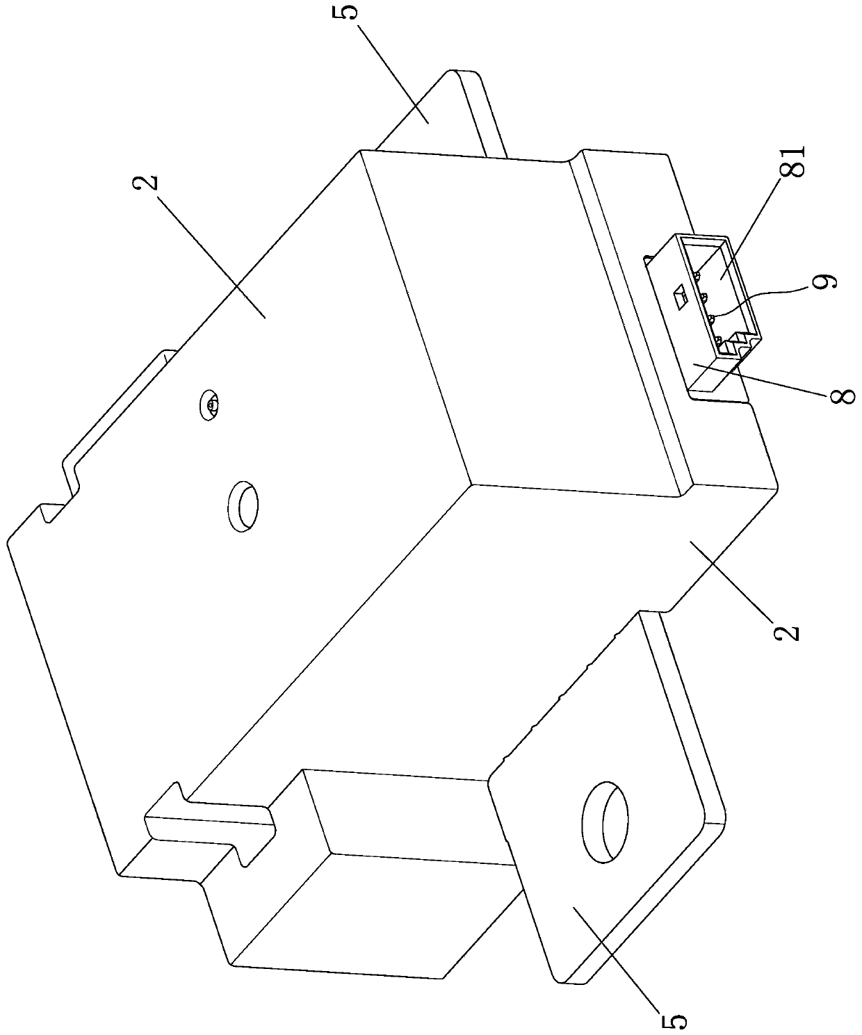
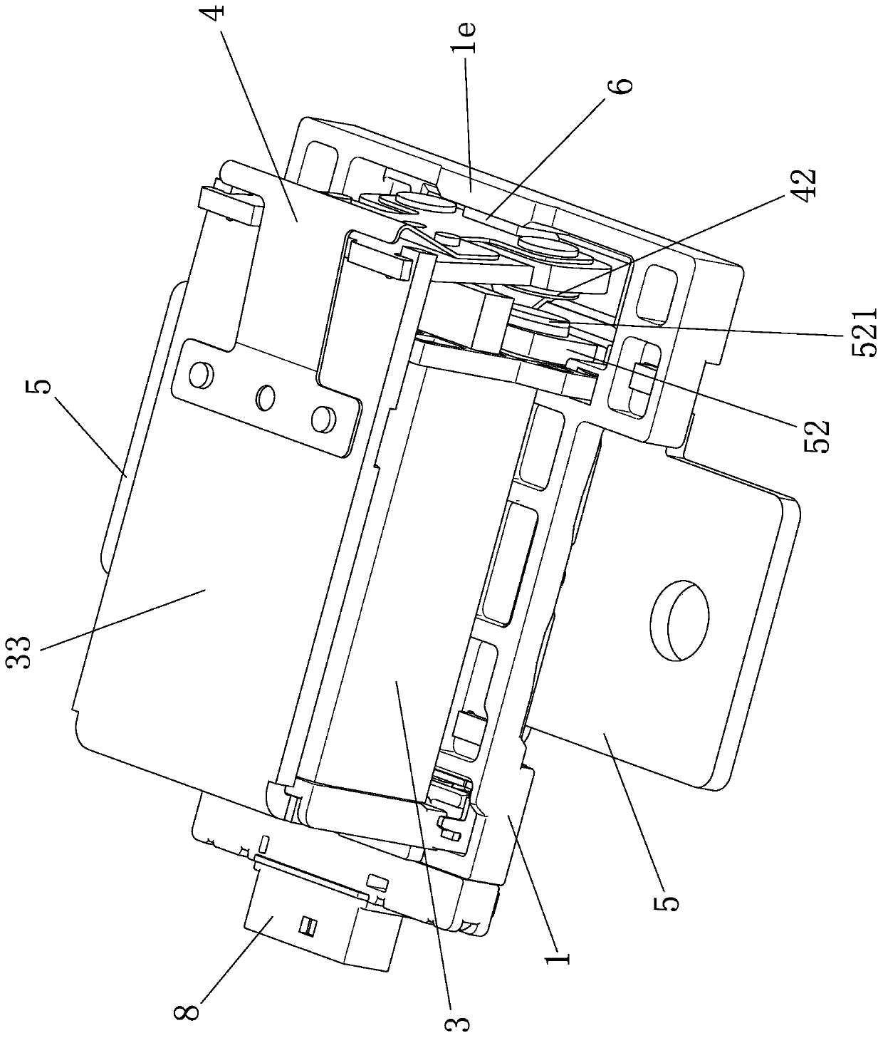
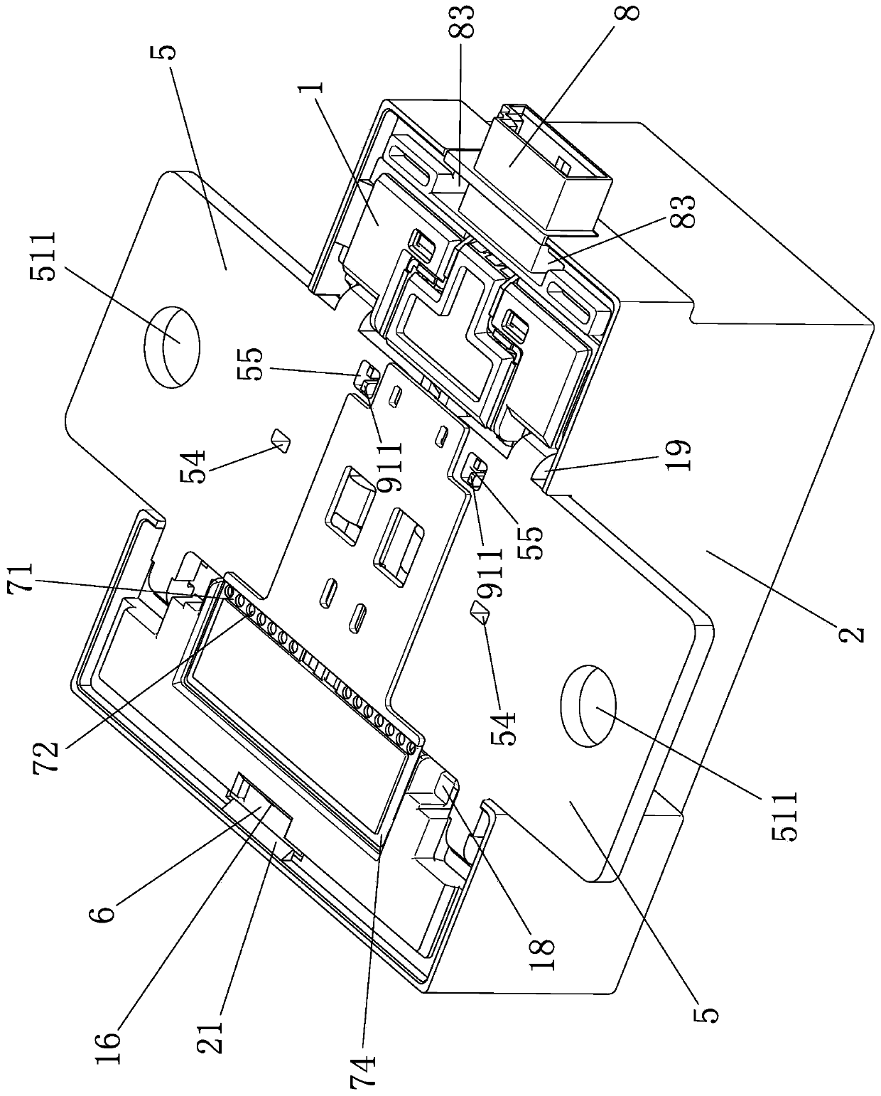
[0063] Embodiment one, Figure 1 to Figure 18 As shown, an electromagnetic relay includes a base 1, a casing 2, a coil 3, a moving reed 4 and two static reeds 5, the casing 2 is clamped and fixedly connected to the base 1, and the inner lower part of the casing 2 is provided with three One clamping limit part 21, three clamping limit parts 21 clamp the base 1, the coil 3 is wound on the coil bobbin 31, the coil bobbin 31 is fixedly connected with the base 1, the coil 3, the coil bobbin 31, and the moving reed 4 Located between the base 1 and the case 2, an iron core 32 is installed in the center hole of the bobbin 31, and a yoke 33 is fixedly connected to the bobbin 31. The yoke 33 is L-shaped, and one end of the yoke 33 is fixedly connected to the bobbin 31. On one side, the other end of the yoke 33 is parallel to the coil 3, and one end of the yoke 33 is provided with two first clipping fixing feet 331, and the lower part of the other side of the coil frame 31 is provided wi...

Embodiment 2

[0088] Embodiment two, Figure 19 to Figure 30 As shown, an electromagnetic relay includes a base 1, a case 2, a coil 3, a moving reed 4 and two static reeds 5, the case 2 is fixedly connected to the base 1, and the coil 3 is wound on a bobbin 31. The coil bobbin 31 is fixedly connected with the base 1, the coil bobbin 31 is located between the base 1 and the cover 2, the center hole of the coil bobbin 31 is equipped with an iron core 32, the coil bobbin 31 is fixedly connected with a yoke 33, and the yoke 33 is L One end of the yoke 33 is fixed to one side of the coil frame 31, the other end of the yoke 33 is parallel to the axial direction of the coil 3, the moving reed 4 is bent along the middle part, and one end of the moving reed 4 is fixed to the yoke 33 On the other end of the moving reed 4, the other end of the moving reed 4 is fixedly connected with an armature 41, and the other end of the moving reed 4 is also provided with two moving contacts 42.

[0089] Each stat...


PUM


Abstract

The invention discloses an electromagnetic relay, which comprises a base, a housing, a coil, a movable reed and two static reeds. The housing is fixedly connected with the base. The coil is located between the base and the housing. The movable reed is provided with a plurality of movable contacts. Each static reed comprises a plate-shaped base part, part of one side of each plate-shaped base partextends outwards and is bent to form a static contact fixing part, and a static contact is fixedly arranged on each static contact fixing part. The base is provided with avoiding through holes. The two static reeds are fixedly connected to the outer side face of the base at intervals through the plate-shaped base parts respectively, each static contact fixing part stretches into the position between the base and the housing through one avoiding through hole, and each static contact corresponds to one movable contact on the movable reed. The plate-shaped base part on each static reed partiallyextends out of the housing to form a connecting part. According to the invention, the heat dissipation effect of the static reed is well improved, the performance of the relay is improved, the preparation process is simplified, the preparation cost is reduced, and the service life of the relay is prolonged.

Description

technical field [0001] The invention relates to the technical field of relay manufacturing, in particular to an electromagnetic relay. Background technique [0002] Electromagnetic relay is an electronic control device, which has a control system (also known as input circuit) and a controlled system (also known as output circuit), usually used in automatic control circuits, it actually uses a smaller current, lower An "automatic switch" that controls a larger current and a higher voltage with a higher voltage. Therefore, it plays the role of automatic adjustment, safety protection, and conversion circuit in the circuit. [0003] Electromagnetic relays, especially snap-in relays, usually include a base, a cover, a coil, a moving reed and two static reeds. The cover is fixedly connected to the base, and the coil is wound on the bobbin. The center hole of the frame is equipped with an iron core, the coil frame is fixedly connected with a yoke, the middle of the moving reed is...

Claims


Application Information

Patent Timeline
Patent Type & Authority Applications(China)
IPC IPC(8): H01H50/54H01H50/02H01H50/12
CPCH01H50/02H01H50/12H01H50/54H01H2050/028
Inventor 魏连贵
Owner XIAMEN HONGFA AUTOMOTIVE ELECTRONICS CO LTD
Why Eureka
Try Eureka