A kind of extensible flexible radio frequency microstrip line and its preparation method

A microstrip line, flexible technology, applied in the field of flexible radio frequency microstrip line and its preparation, can solve the problem of no flexible microstrip line preparation process and the like

Active Publication Date: 2021-07-06
UNIV OF ELECTRONICS SCI & TECH OF CHINA
View PDF7 Cites 0 Cited by
  • Summary
  • Abstract
  • Description
  • Claims
  • Application Information

AI Technical Summary

Problems solved by technology

However, there is currently no fabrication process for flexible microstrip lines

Method used


Image

  • A kind of extensible flexible radio frequency microstrip line and its preparation method
  • A kind of extensible flexible radio frequency microstrip line and its preparation method
  • A kind of extensible flexible radio frequency microstrip line and its preparation method

Examples


Embodiment 1

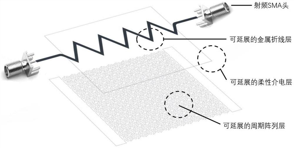
[0039] A method for preparing an extensible flexible radio frequency microstrip line, the specific process is as follows figure 2 As shown, it specifically includes the following steps:

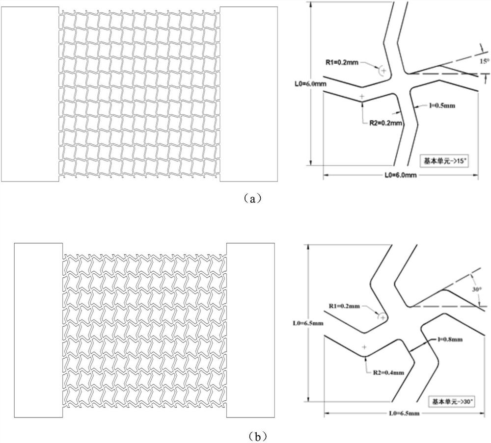
[0040] Step 1: Choose a thermal release adhesive at 120 degrees Celsius, stick the thermal release adhesive on the copper clad surface of the polyimide copper clad film, and use an engraving machine to engrave the thermal release adhesive to form an extensible periodic array layer and The pattern of the stretchable metal fold line layer, wherein the angle between the first strip and the horizontal line in the basic array unit of the stretchable periodic array layer is 15°, and the angle between the first strip and the second strip is The included angle β is 130°, the radius R1 of the inner chamfer and the radius of the outer chamfer R2 between the first long strip and the second long strip are both 0.2 mm, and the center point between two adjacent basic array units The distance between the ...

Embodiment 2

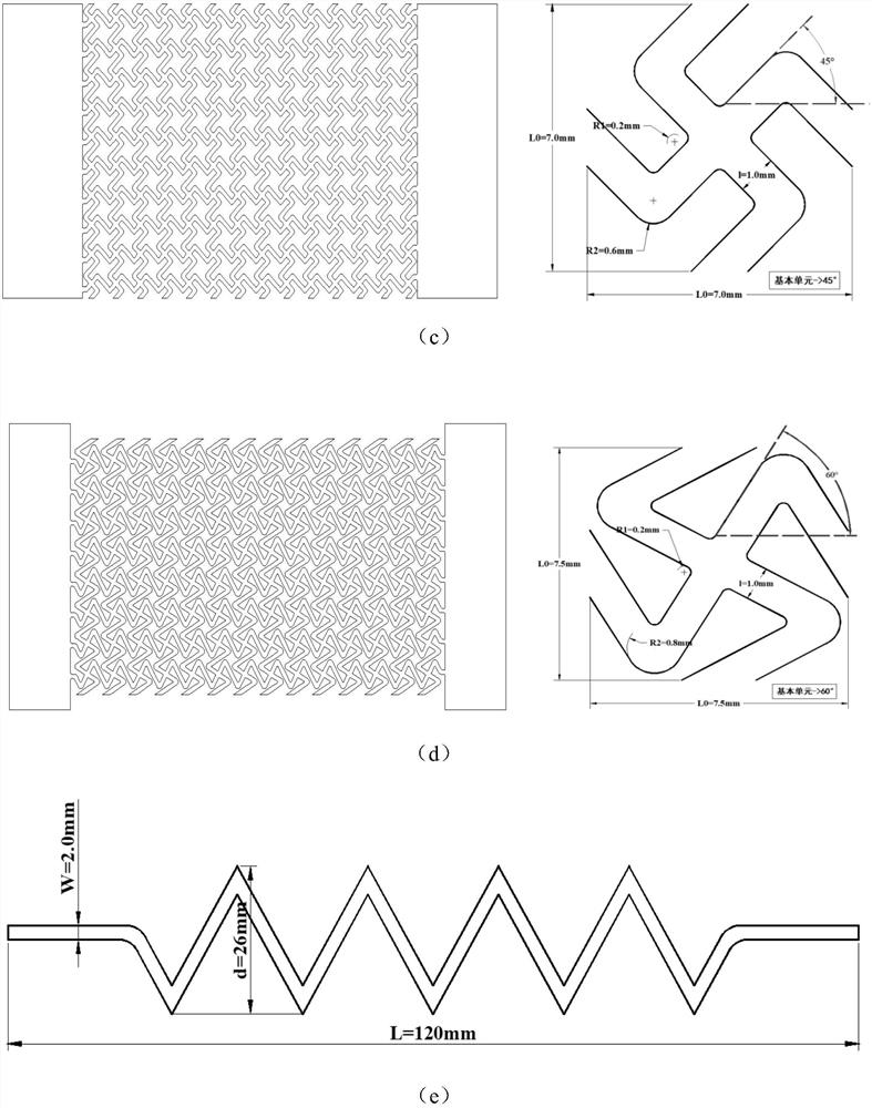
[0049] According to the steps of Example 1 to prepare a stretchable flexible radio frequency microstrip line, only the angle between the first strip and the horizontal line in the basic array unit of the stretchable periodic array layer in step 1 is adjusted to 30°, 45° and 60°, the distance between the center points of two adjacent basic array units is adjusted to 6.5mm, 7.0mm and 7.5mm, the radius of the inner chamfer between the first strip and the second strip R1 is 0.2mm, the radius R2 of the outer chamfer is adjusted to 0.4mm, 0.6mm, and 0.8mm, and the width of the strip is adjusted to 0.8mm, 1.0mm, and 1.0mm respectively, and other steps remain unchanged.

[0050] The left and right ends of the extensible flexible radio frequency microstrip line obtained in embodiment 1 and embodiment 2 are welded with SMA radio frequency terminal blocks, and then the whole device is placed in a vector network analyzer for measurement, and the S of the device is obtained. 11 and S 21 T...


PUM


Abstract

The invention provides an extensible flexible radio frequency microstrip line and a preparation method thereof, which belong to the technical field of flexible electronics. The flexible radio frequency microstrip line prepared by the present invention adopts a sandwich structure consisting of three layers: an extensible metal fold line layer, an extensible flexible dielectric layer, and an extensible periodic array layer. On the one hand, the invention achieves relatively good signal transmission performance, and the signal quality within 0-3GHz can be guaranteed; on the other hand, the invention achieves relatively good ductility, and the signal is No obvious attenuation will occur. In summary, the present invention will shine brilliantly in the fields of wireless communication and bioelectronic medical treatment in the future.

Description

technical field [0001] The invention belongs to the technical field of flexible electronics, and in particular relates to an extensible and flexible radio frequency microstrip line and a preparation method thereof. Background technique [0002] Microstrip lines are widely used in mobile phone circuits, and generally have two functions: one is to transmit high-frequency signals more effectively; the other is to form a matching network with other solid devices such as inductors and capacitors to make the signal output The terminal and the load are well matched, and the power can be consumed by the line as little as possible and delivered to the load as much as possible. The traditional microstrip line structure is a microwave transmission line composed of a single conductor strip supported on a rigid dielectric substrate. The other side of the substrate is made of a grounded metal plate. It is the basis of microwave integrated circuits and is widely used in microwave integrate...

Claims


Application Information

Patent Timeline
Patent Type & Authority Patents(China)
IPC IPC(8): H01P3/10H01P3/18H01P11/00
CPCH01P3/10H01P3/18H01P11/003
Inventor 潘泰松彭越禹陈思宏谷雨颜卓程高敏林媛
Owner UNIV OF ELECTRONICS SCI & TECH OF CHINA
Why Eureka
Try Eureka