
Over-current protection circuit

An over-current protection circuit and over-current protection technology, applied in the direction of emergency protection circuit devices, circuits, circuit devices, etc., can solve problems such as inferior reliability to hardware circuits, simple functions, and poor real-time performance, and achieve flexible software control and adjustable parameters. Adjust and ensure the effect of stable work

Pending Publication Date: 2020-02-14
鉴丰电子科技有限公司
View PDF0 Cites 8 Cited by
  • Summary
  • Abstract
  • Description
  • Claims
  • Application Information

AI Technical Summary

Problems solved by technology

The advantages of the hardware protection circuit are good real-time performance and fast response speed, but the function is simple, generally it is current limiting protection
Due to the participation of software control, the protection circuit of hardware plus software has better protection function, but the real-time performance is slightly worse, and the overall reliability is not as good as that of hardware circuit.

Method used


Image

  • Over-current protection circuit
  • Over-current protection circuit

Examples


Embodiment

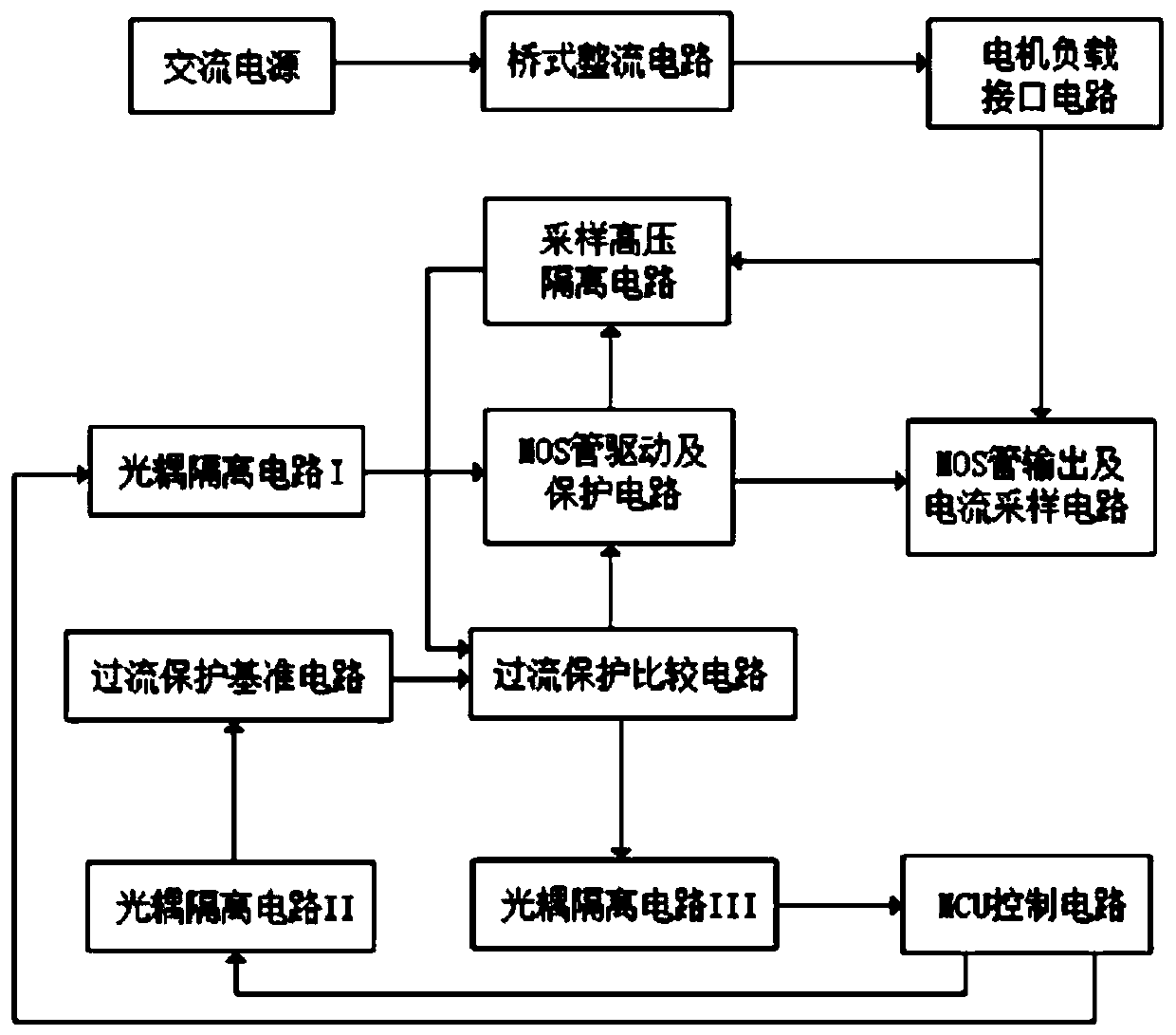
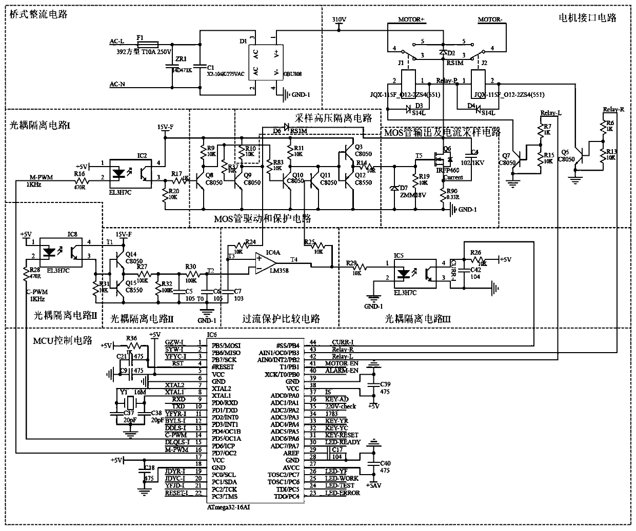
[0018] Example: such as figure 1 As shown, an overcurrent protection circuit consists of bridge rectifier circuit, motor load interface circuit, MOS tube output and current sampling circuit, sampling high voltage isolation circuit, MOS tube drive and protection circuit, overcurrent protection comparison circuit, MCU control circuit, Overcurrent protection reference circuit, optocoupler isolation circuit I, optocoupler isolation circuit II, optocoupler isolation circuit III. The bridge rectifier circuit is connected to the alternating current, which is rectified by the bridge rectifier circuit and then input to the motor load interface circuit; the motor load interface circuit is respectively connected to the sampling high voltage isolation circuit, the MOS tube output and the current sampling circuit; the MOS tube drive and protection circuit are respectively connected to the sampling high voltage Isolation circuit, MOS tube output and current sampling circuit, overcurrent pro...


PUM


Abstract

The invention relates to an over-current protection circuit, which includes a bridge rectifier circuit, a motor load interface circuit, an MOS tube output and current sampling circuit, a sampling high-voltage isolation circuit, an MOS tube drive and protection circuit, an over-current protection comparison circuit, an MCU control circuit, an over-current protection reference circuit, an optocoupler isolation circuit I, an optocoupler isolation circuit II and an optocoupler isolation circuit III. Power drive over-current protection can be realized; since respective advantages of hardware circuit and software control are combined, the circuit of the invention has fast response and reliable action of a hardware circuit and also has flexibility of software control and adjustable parameters; and a PWM signal and an over-current protection signal between the MCU control circuit and the MOS tube drive and protection circuit are isolated by an optocoupler without electrical interference, thusensuring the stable operation of the MCU circuit.

Description

technical field [0001] The invention relates to the technical field of protection circuits, in particular to an overcurrent protection circuit. Background technique [0002] In terms of power electronics technology, new semiconductor power devices are widely used because of their high power, high speed, small size and simple control. However, semiconductor devices also have their inherent disadvantages, that is, poor overload capacity, insufficient impact resistance, and are easily damaged by a slight overvoltage or overcurrent. Among them, the overcurrent protection is the key point, and the technical difficulty is relatively large. General overcurrent protection circuits include hardware circuits and hardware plus software circuits. The advantage of the hardware protection circuit is that it has good real-time performance and fast response speed, but its function is simple, and it is generally current-limiting protection. Due to the participation of software control, th...

Claims


Application Information

Patent Timeline
Patent Type & Authority Applications(China)
IPC IPC(8): H02H3/087H02H7/085H03K17/082
CPCH02H3/087H02H7/0854H03K17/0822
Inventor 王庆陈友坚
Owner 鉴丰电子科技有限公司
Learn More