Marine charging device
A charging device and marine technology, applied in circuit devices, battery circuit devices, charging stations, etc., can solve the problems of high labor cost, low charging efficiency, high labor intensity, etc., so as to reduce labor costs and save the time required for connection , the effect of reducing labor intensity
Pending Publication Date: 2020-02-14
上海润通电动车技术有限公司 +1
0 Cites 2 Cited by
AI-Extracted Technical Summary
Problems solved by technology
This charging method has low reliability, high labor cost, h...
Method used
[0076] Specifically, as shown in FIG. 5 , FIG. 8 , and FIG. 9 , the docking guide mechanism 103 includes a guide assembly 1032 and a docking assembly 1031. Wherein, the guide assembly 1032 includes a support plate 10322 located below the automatic charging interface 101, the top of the support plate 10322 is provided with a chute 10321, the bottom of the chute 10321 is arranged with rollers 10323, and the bottom of the automatic charging plug 204 is provided with a guide plate 2041, The guide plate 2041 slides along the sliding groove 10321 on the roller 10323, which can reduce friction during sliding.
[0087] The present invention arranges the automatic charging interface 101 in the dock...
Abstract
The invention discloses a marine charging device, and belongs to the technical field of ship charging. The marine charging device comprises an automatic charging interface and an automatic charging plug matched with the automatic charging interface. The marine charging device further comprises a butt joint bin, a charging room, a positioning mechanism and a clamping mechanism. The butt joint bin is arranged on a ship, and the automatic charging interface is arranged in the butt joint bin. The automatic charging plug is arranged in the charging room. The positioning mechanism is arranged in thecharging room, and the positioning mechanism is configured to determine the position of the automatic charging interface. The clamping mechanism is arranged in the charging room and used for clampingthe automatic charging plug, and the clamping mechanism can insert the automatic charging plug into the automatic charging interface according to the position information of the automatic charging interface determined by the positioning mechanism and can move the automatic charging plug out of the automatic charging interface. According to the invention, automatic charging of a ship is realized,the labor intensity is reduced, the labor cost is reduced, the safety is improved, and the charging efficiency is improved.
Application Domain
Charging stationsElectric power +3
Technology Topic
Electrical and Electronics engineeringMarine engineering +1
Image
Examples
- Experimental program(1)
Example Embodiment
[0052] Embodiments of the present invention are described in detail below, and examples of the embodiments are shown in the drawings, wherein the same or similar reference numerals denote the same or similar elements or elements having the same or similar functions throughout. The embodiments described below by referring to the figures are exemplary and are intended to explain the present invention and should not be construed as limiting the present invention.
[0053]In the description of the present invention, it should be noted that the terms "center", "upper", "lower", "left", "right", "vertical", "horizontal", "inner", "outer" etc. The indicated orientation or positional relationship is based on the orientation or positional relationship shown in the drawings, and is only for the convenience of describing the present invention and simplifying the description, rather than indicating or implying that the referred device or element must have a specific orientation, or in a specific orientation. construction and operation, therefore, should not be construed as limiting the invention. In addition, the terms "first" and "second" are used for descriptive purposes only, and should not be understood as indicating or implying relative importance. Wherein, the terms "first position" and "second position" are two different positions.
[0054] Unless otherwise clearly specified and limited, the terms "mounted", "connected", "connected" and "fixed" should be interpreted in a broad sense, for example, it may be a fixed connection or a detachable connection; it may be a mechanical connection, or It can be an electrical connection; it can be a direct connection, or an indirect connection through an intermediary, and it can be an internal communication between two elements or an interaction relationship between two elements. Those of ordinary skill in the art can understand the specific meanings of the above terms in the present invention according to specific situations.
[0055] Unless otherwise expressly specified and limited, a first feature being "on" or "under" a second feature may include that the first feature is in direct contact with the second feature, and may also include that the first feature and the second feature are not in direct contact. Rather, through additional characteristic contacts between them. Moreover, "above", "above" and "above" the first feature on the second feature include that the first feature is directly above and obliquely above the second feature, or simply means that the first feature is horizontally higher than the second feature. "Below", "beneath" and "under" the first feature to the second feature include that the first feature is directly below and obliquely below the second feature, or simply means that the first feature has a lower level than the second feature.
[0056] Attached below Figure 1-11 The technical solutions of the present invention are further described through specific implementation methods.
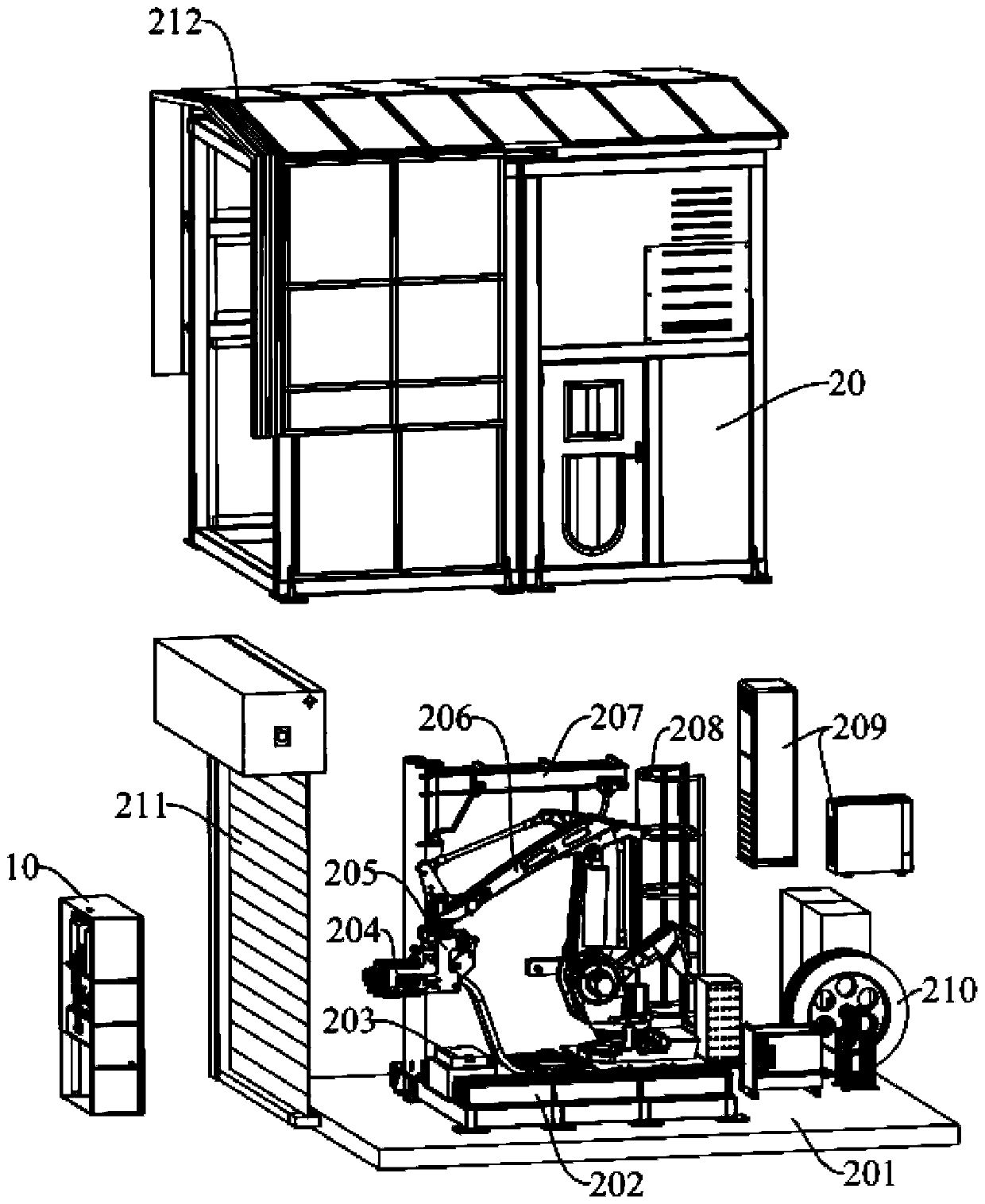
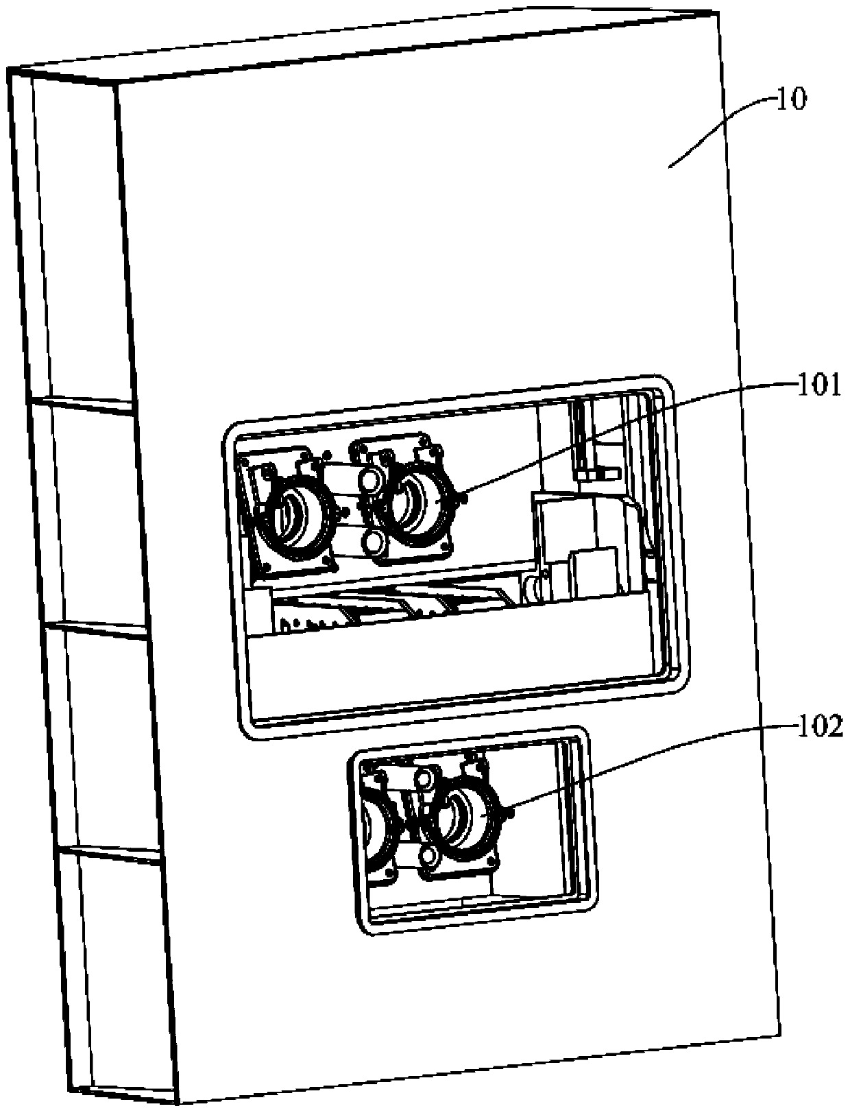
[0057] The marine charging device provided in this embodiment includes a charging interface and a charging plug connected to a power supply. When charging, the charging interface can be matched and connected to the charging plug for charging. In order to facilitate ship charging, improve the efficiency and safety of ship charging, reduce labor intensity, and reduce labor costs, such as Figure 1 to Figure 3 As shown, the charging interface includes an automatic charging interface 101, and the charging plug includes an automatic charging plug 204 that matches the automatic charging interface 101. The automatic charging plug 204 is used to automatically insert or pull out the automatic charging interface 101, thereby realizing automatic charging.
[0058] In order to realize the above-mentioned automatic charging, the marine charging device also includes a docking bin 10 , a charging room 20 , a positioning mechanism (not shown) and a clamping mechanism 205 .
[0059] The docking bin 10 is set on the ship, and the automatic charging interface 101 is set in the docking bin 10 . When the ship needs to be charged, the ship docks so that the docking chamber 10 faces the shore, so as to facilitate docking with the equipment on the shore.
[0060] The automatic charging plug 204 , the positioning mechanism and the clamping mechanism 205 are all arranged in the charging room 20 . Wherein, the positioning mechanism is configured to determine the position of the automatic charging interface 101 . The clamping mechanism 205 is used for clamping the automatic charging plug 204 . The clamping mechanism 205 can insert the automatic charging plug 204 into the automatic charging interface 101 according to the position information of the automatic charging interface 101 determined by the positioning mechanism, and can move the automatic charging plug 204 out of the automatic charging interface 101 after charging is completed.
[0061] In this embodiment, when the ship needs to be charged, after the corresponding charging room 20 docks, the positioning mechanism can determine the position of the automatic charging interface 101 in the docking compartment 10. According to the position information determined by the positioning mechanism, the clamping mechanism 205 will automatically charge the charging plug. 204 corresponds to the insertion of the automatic charging interface 101 . After the charging is completed, the clamping mechanism 205 clamps the automatic charging plug 204 to move out of the automatic charging interface 101, and moves into the charging room 20, thereby realizing the automatic charging of the ship, reducing the time for docking the charging plug and the charging interface, and improving the charging efficiency. Efficiency, reliability and safety, reduced labor intensity, and saved labor costs.
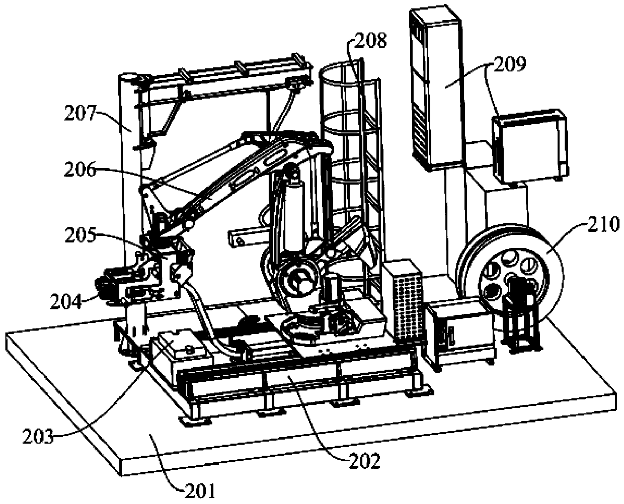
[0062] Due to the high frequency of ship charging and the use environment is outdoors, it is easily affected by external factors such as weather, which may cause failures during use. When the automatic charging fails, in order to enable the ship to charge normally, such as figure 2 , image 3 As shown, the charging interface further includes a manual charging interface 102 disposed below the automatic charging interface 101 , and the manual charging interface 102 is disposed below, which is convenient for personnel to operate. The charging plug (not shown) also includes a manual charging plug matched with the manual charging interface 102 , and the manual charging plug is arranged in the charging room 20 . Specifically, an industrial booster arm 207 is provided in the charging room 20 , and a manual charging plug is set on the industrial booster arm 207 , and the manual charging plug is inserted into the manual charging interface 102 with the assistance of the industrial booster arm 207 .
[0063] Therefore, the marine charging device of the present invention has two charging methods, automatic charging and manual charging, which can meet different charging needs and have a wide range of applications.
[0064] In order to facilitate the understanding of the implementation form of automatic charging, the part of automatic charging will be introduced in detail below.
[0065] In this embodiment, the positioning mechanism includes a laser scanner (not shown), and the laser scanner is arranged in the charging room 20 and close to the side of the automatic rolling door 211 . The laser scanner can be SICK's LMS51 laser scanner, which can accurately locate the automatic charging interface 101 of the ship, so as to obtain the position information of the automatic charging interface 101 of the ship to be charged, and the position information is used for accurate operation of the clamping mechanism 205 .
[0066] In this example, if Figure 4 As shown, the clamping mechanism 205 includes a body 2053 , a fixed plate 2051 and a movable plate 2052 , and a fixed plate 2051 is provided on both sides of the body 2053 . Both sides of the main body 2053 are provided with a movable plate 2052 inside the fixed plate 2051 . A fixing groove 2054 capable of clamping and releasing the second roller 2043 is formed between the movable plate 2052 and the fixed plate 2051 on the same side.
[0067] Specifically, one side of the fixed plate 2051 is provided with a U-shaped groove, and the middle of the bottom of the U-shaped groove is recessed to form a semi-arc groove. The movable plate 2052 is provided with a lug 20521 corresponding to the opening of the half-arc groove. The arc-shaped groove cooperates to form a fixing groove 2054 .
[0068] The movable plate 2052 and the fixed plate 2051 are connected by a connecting rod assembly, and the movable plate 2052 is driven to swing relative to the fixed plate 2051 by the connecting rod assembly, so as to change the size of the opening of the fixed slot 2054 .
[0069] In order to facilitate the clamping mechanism 205 to clamp the automatic charging plug 204, as Figure 5 , Image 6 As shown, a second roller 2043 is respectively provided on both sides of the automatic charging plug 204 . When it is necessary to insert the automatic charging plug 204 into the automatic charging interface 101, the clamping mechanism 205 clamps the automatic charging plug 204, specifically, the clamping mechanism 205 opens the fixing groove 2054, so that the second roller 2043 is snapped into the fixing groove 2054 to realize Clamping; when the automatic charging plug 204 reaches the specified position, such as after being inserted into the automatic charging interface 101, and returns to the initial position, the fixing groove 2054 is opened, and the second roller 2043 is released to realize separation.
[0070] Further, a sensor 20511 is provided on the fixing plate 2051 corresponding to the fixing groove 2054 , and the sensor 20511 is configured to detect whether the second roller 2043 is clamped in the fixing groove 2054 . When the automatic charging plug 204 needs to be removed from the automatic charging interface 101 , the sensor 20511 can determine whether the clamping mechanism 205 clamps the automatic charging plug 204 in place.
[0071] In order to enable the clamping mechanism 205 to better cooperate with the positioning mechanism to insert the automatic charging plug 204 into the automatic charging interface 101, as Figure 1 to Figure 3 As shown, the marine charging device also includes an industrial robot 206 , and the industrial robot 206 is set in the charging room 20 . The clamping mechanism 205 is connected to the hand of the industrial robot 206 . After the positioning mechanism determines the position information of the automatic charging interface 101, the industrial robot 206 drives the clamping mechanism 205 to move the automatic charging plug 204 to the automatic charging interface 101 according to the position information, and inserts the automatic charging plug 204 into the automatic charging interface 101. After the industrial robot 206 drives the clamping mechanism 205 to insert the automatic charging plug 204 into the automatic charging interface 101, it returns to the charging room 20 to complete the charging operation; Pull out the automatic charging interface 101 and return to the charging room 20 again.
[0072] In order to ensure that the clamping mechanism 205 can operate accurately every time, as image 3 As shown, the marine charging device also includes a return mechanism 203, which is arranged in the charging room 20, and the return mechanism 203 is configured to replace the automatic charging plug 204 after the automatic charging plug 204 is inserted into the automatic charging interface 101 and the charging is completed. After the 204 is moved out, the industrial robot 206 drives the clamping mechanism 205 to return to the initial position, so that the clamping mechanism 205 can accurately position the automatic charging plug 204 when it is pulled out or recharged. Specifically, the return mechanism 203 includes a reference base provided in the charging room 20 , and the clamping mechanism 205 can return to the initial position through the positional relationship information between the initial position of the clamping mechanism 205 and the reference base.
[0073] In order to facilitate the accurate movement of the industrial robot 206, such as Figure 7 As shown, the marine charging device further includes a moving mechanism 202 configured to drive an industrial robot 206 to move back and forth toward the ship. The moving mechanism 202 is disposed on the bottom plate 201 of the charging room 20 . The mobile mechanism 202 is an industrial slide table, and the industrial slide table includes a gear driven by a motor, a rack 2022 matched with the gear, a linear slide rail 2021 and a robot mount 2023, and the robot mount 2023 is arranged above the linear slide rail 2021 and The slider connected to the linear slide rail 2021, the rack 2022 is arranged on one side of the linear slide rail 2021, and the motor is arranged on the robot mounting base 2023 and connected to the gear. The motor drives the gear to rotate, and the gear meshes with the rack 2022 to drive the robot mounting base 2023 to slide along the linear slide rail 2021 .
[0074] In practical applications, when the industrial robot 206 moves toward the ship, the charging cable stretches back and forth for a long time, in order to facilitate the management of the charging cable, as figure 1 , image 3 As shown, the marine charging device also includes a cable retractable mechanism, which is arranged in the charging room 20 , and the cable retractable mechanism is configured to automatically release or tighten the charging cable connected to the automatic charging plug 204 . Optionally, the cable retracting mechanism is a winch 210 .
[0075] When the clamping mechanism 205 clamps the automatic charging plug 204 and enters the automatic charging interface 101 according to the position information of the automatic charging interface 101 determined by the positioning mechanism, it is avoided that the automatic charging plug 204 cannot be accurately aligned and inserted into the automatic charging due to the floating of the ship. interface 101, such as Figure 8 , the marine charging device further includes a docking guide mechanism 103 , the docking guide mechanism 103 can be docked with the automatic charging plug 204 and guide the automatic charging plug 204 to be inserted into the automatic charging interface 101 .
[0076] Specifically, such as Figure 5 , Figure 8 , Figure 9As shown, the docking guide mechanism 103 includes a guide assembly 1032 and a docking assembly 1031 . Wherein, the guide assembly 1032 includes a support plate 10322 located below the automatic charging interface 101, the top of the support plate 10322 is provided with a chute 10321, the bottom of the chute 10321 is arranged with rollers 10323, and the bottom of the automatic charging plug 204 is provided with a guide plate 2041, The guide plate 2041 slides along the sliding groove 10321 on the roller 10323, which can reduce friction during sliding.
[0077] When the automatic charging plug 204 is inserted into the automatic charging interface 101, the docking assembly 1031 can dock with the automatic charging plug 204 and drive the automatic charging plug 204 to be inserted into the automatic charging interface 101; when the automatic charging plug 204 is moved out of the automatic charging interface 101, the docking assembly 1031 can Release the automatic charging plug 204 after the automatic charging plug 204 is moved out of the automatic charging interface 101 .
[0078] Further, the two sides of the automatic charging plug 204 are respectively provided with a first roller 2042, the docking assembly 1031 includes a moving plate 10315, a first vertical plate 10312 and a second vertical plate 10311, the moving plate 10315 is located under the supporting plate 10322, and the moving plate 10315 can move back and forth relative to the support plate 10322 along the connection direction between the automatic charging plug 204 and the automatic charging interface 101 . The two first vertical plates 10312 are located on both sides of the moving plate 10315 respectively. The second vertical plate 10311 is arranged at intervals on one side of the first vertical plate 10312 and can slide up and down relative to the first vertical plate 10312 . Optionally, the length of the second vertical plate 10311 is shorter than that of the first vertical plate 10312 .
[0079] When the clamping mechanism 205 clamps the automatic charging plug 204 and inserts it into the automatic charging interface 101, when the automatic charging plug 204 reaches the automatic charging interface 101, the first roller 2042 crosses the second vertical plate on the top of the second vertical plate 10311. The step from the plate 10311 to the side of the first vertical plate 10312. At this time, the second vertical plate 10311 slides upwards along the first vertical plate 10312 to clamp the first roller 2042 between the first vertical plate 10312 and the second vertical plate 10311 to realize the positioning of the automatic charging plug 204; after positioning , the industrial robot 206 and the clamping mechanism 205 are further pushed, thereby moving the automatic charging plug 204 together with the docking assembly 2031 until the automatic charging plug 204 is inserted into the automatic charging interface 101 . On the contrary, when the automatic charging plug 204 moves out of the automatic charging interface 101, the clamping mechanism 205 drives the automatic charging plug 204 and the docking assembly 1031 to move outwards, and when the second vertical plate 10311 reaches the initial position, it automatically slides downward to The clamping of the first roller 2042 is released, and the first roller 2042 is disengaged from between the first vertical plate 10312 and the second vertical plate 10311 .
[0080] In order to make the second vertical plate 10311 automatically slide along the first vertical plate 10312 during the movement of the moving plate 10315, a second guide plate 10313 is respectively arranged on both sides of the moving plate 10315, and a The second guide groove 10314 extends along the moving direction of the moving plate 10315, and the second guide groove 10314 is recessed downward at one end close to the entrance of the automatic charging interface 101, forming a stepped groove. A cam bearing is connected between the second vertical plate 10311 and the second guide groove 10314 . The bearing end of the cam bearing is rollingly connected in the second guide groove 10314 .
[0081] Before the automatic charging plug 204 is inserted into the automatic charging interface 101 , the moving plate 10315 drives the first vertical plate 10312 and the second vertical plate 10311 to move outward until the bearing end of the cam bearing is located at the lower position of the second guide groove 10314 . After docking with the first roller 2042 , the moving plate 10315 drives the first vertical plate 10312 and the second vertical plate 10311 to move along the second guide groove 10314 until the bearing end of the cam bearing is located at the level of the second guide groove 10314 . Thereby, automatic up and down sliding, automatic docking and disengagement of the first vertical plate 10312 can be realized.
[0082] In order to facilitate determining whether the automatic charging plug 204 is inserted into the automatic charging interface 101 , limit switches are provided on the support plate 10322 along the front and back of the docking direction of the automatic charging plug 204 and the automatic charging interface 101 .
[0083] In order to protect the various components in the charging room 20, such as figure 1 As shown, the side of the charging room 20 corresponding to the ship is provided with a first lift door. Optionally, the first lift door is an automatic rolling door 211 . When not charging, the automatic rolling door 211 is lowered to close the charging room 20; when charging, the automatic rolling door 211 is raised to make the charging room 20 open.
[0084] In addition, since the ship is close to the charging room 20, it is avoided that the ship hits the charging room 20, such as figure 1 , Figure 10 As shown, the side of the charging room 20 facing the ship is provided with a protective cover 212 . The protective cover 212 can stretch out when the automatic charging plug 204 is inserted into the automatic charging interface 101 and shrink after charging is completed. The protective cover 212 is correspondingly arranged on the top and both sides of the automatic rolling door 211, and the two sides of the protective cover 212 are respectively connected to a side plate 213, and the side plate 213 is slidably connected to the charging room 20 along the direction toward the ship. When the ship is charging, the side plate 213 moves toward the ship and the protective cover 212 stretches out, which can prevent the ship from strongly colliding with the charging room 20, and at the same time play a role in protecting the charging plug protruding through the automatic rolling door 211 from sun protection and protection. The effect of rain.
[0085] In order to facilitate the maintenance and repair of the equipment in the charging room 20 , a climbing ladder 208 is also provided in the charging room 20 . In addition, an air conditioner 209 is also provided in the charging room 20 to regulate the temperature and humidity in the charging room 20 .
[0086] When the ship does not need to be charged, in order to protect the components in the automatic charging interface 101, such as Figure 8 , Figure 11 As shown, a second lift gate 104 is provided corresponding to the automatic charging interface 101 , and a lift mechanism 105 is connected to the second lift gate 104 . The lifting mechanism 105 includes a mounting plate 1053, a first guide plate 1052 and a transmission assembly 1051. A mounting plate 1053 is respectively arranged on both sides of the second lifting door 104. The mounting plate 1053 is fixed in the docking compartment 10, and one mounting plate 1053 is correspondingly connected to a The first guide plate 1052, the first guide plate 1052 is located on the inner side of the two mounting plates 1053 and on the side close to the second lifting door 104, the first guide plate 1052 is vertically provided with a first guide groove 10521, the first guide The slot 10521 and the second lifting door 104 are connected by a cam bearing so that the second lifting plate 104 slides up and down along the first guide slot 10521 . The transmission assembly 1051 includes a screw rod, a screw nut and a guide rail connected to the screw nut, the second lifting door 104 is connected to the slider of the guide rail, and the screw rod is arranged on the side of the mounting plate 1053 that is not connected to the first guide plate 1052 . Both ends of the first guide groove 10521 are recessed toward the outside of the docking bin 10 . When the second lifting door 104 needs to be lifted, the screw rod is driven to rotate, and the screw nut drives the second lifting door 104 to lift through the guide rail. Under the guidance of the first guide groove 10521, the second lifting door 104 can rise and fall stably. The two sides of a guide groove 10521 are recessed toward the outside of the docking bin 10, so that the second lifting door 104 is not easy to lift under the action of external force when it is in the highest position and the lowest position.
[0087] In the present invention, an automatic charging interface 101 is provided in the docking compartment 10, an automatic charging plug 204 is provided in the charging room 20, the position information of the automatic charging interface 101 is determined by a positioning mechanism, and the automatic charging plug 204 and the automatic charging interface are automatically charged through the docking guide mechanism 103. The docking of the interface 101 is more precise, and the automatic charging plug 204 clamped by the clamping mechanism 205 driven by the industrial robot 206 is inserted into the automatic charging interface 101. At the same time, the cable retractable mechanism makes the charging cable easier to manage, thereby realizing the automatic charging of the ship. In addition, the setting of the manual charging interface and the manual charging plug enables the ship to be charged normally when the automatic charging fails.
[0088] Apparently, the above-mentioned embodiments of the present invention are only examples for clearly illustrating the present invention, rather than limiting the implementation of the present invention. For those of ordinary skill in the art, other changes or changes in different forms can be made on the basis of the above description. It is not necessary and impossible to exhaustively list all the implementation manners here. All modifications, equivalent replacements and improvements made within the spirit and principles of the present invention shall be included within the protection scope of the claims of the present invention.
PUM


Description & Claims & Application Information
We can also present the details of the Description, Claims and Application information to help users get a comprehensive understanding of the technical details of the patent, such as background art, summary of invention, brief description of drawings, description of embodiments, and other original content. On the other hand, users can also determine the specific scope of protection of the technology through the list of claims; as well as understand the changes in the life cycle of the technology with the presentation of the patent timeline. Login to view more.
Similar technology patents
Full-automatic double-layer bag packaging machine
Owner:JIANGSU WANLE COMPOSITE MATERIAL
Charging bow type electric car charging system
Owner:凯迈(洛阳)电子有限公司
Character image jet-printing, recognition and calibration system and method
Owner:SHANGHAI BAOSIGHT SOFTWARE CO LTD
Upland single-rail orchard transporter
Owner:HUAZHONG AGRICULTURAL UNIVERSITY
Floating type aquatic culture device
Owner:黄平县幺妹滩科技生态有限公司
Classification and recommendation of technical efficacy words
- Reduce labor intensity
- Reduce labor costs
Method for intelligent automatic identification of transmission circuit parts
Owner:INFORMATION COMM COMPANY STATE GRID SHANDONG ELECTRIC POWER +2
City regional railway signal system and control method thereof
Owner:CHINA RAILWAY SIYUAN SURVEY & DESIGN GRP
Railway bearing intelligent on-line detection method and its device
Owner:洛阳铭昊测控科技有限公司
Full-automatic loading-unloading and visual inspection device
Owner:武汉智慧眼智能科技有限公司
Application of male sterility gene OsDPW2 and rice sterility recovery method
Owner:SHANGHAI JIAO TONG UNIV
Multi-network cooperative network optimization and energy saving method and system
Owner:BEIJING TUOMING COMM TECH
Remote after-service on-line ECU refresh method and diagnosis apparatus
Owner:GUANGZHOU XIAOPENG MOTORS TECH CO LTD +1
Logistics robot, method and controller used for logistics robot, and computer readable medium
Owner:LINGDONG TECH BEIJING CO LTD