Reject valve of reverse osmosis device

A technology of reverse osmosis device, discharge valve, applied in the direction of reverse osmosis, valve device, valve operation/release device, etc.

Inactive Publication Date: 2020-02-14
SOLAR WATER SOLUTIONS OY
View PDF5 Cites 0 Cited by
  • Summary
  • Abstract
  • Description
  • Claims
  • Application Information

AI Technical Summary

Problems solved by technology

A practical disadvantage is that the production of the membranes only starts to stabilize after the system has been in use for some time

Method used


Image

  • Reject valve of reverse osmosis device
  • Reject valve of reverse osmosis device
  • Reject valve of reverse osmosis device

Examples


Embodiment Construction

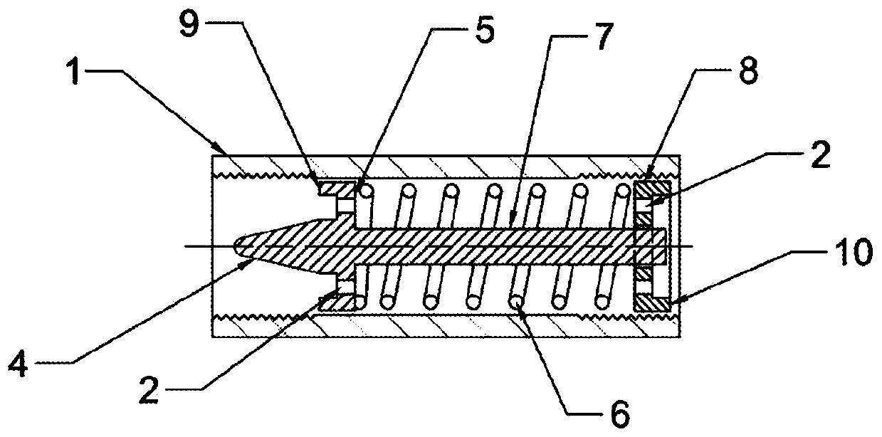
[0021] In the following, refer to the attached Figure 3 to Figure 5 . The invention and the structure of the discharge valve are described by means of examples.

[0022] image 3 A cross-section in the axial direction of the outlet valve is shown. The body 1 comprises freely movable conical needles 4 , 5 , 7 , on whose axis 7 a plate-like element 5 (referred to below as a restrictor plate) is fixedly supported, said plate-like element 5 adjoining the inner wall of the body 1 . On the edge of the restrictor plate 5 on one side of the cone 4 there is an annular gasket 9 or a corresponding protrusion. The guide plate 8 is not attached and adjoins the inner wall of the body 1 at its periphery. In the middle of the guide plate is a hole whose periphery adjoins the shaft 7 of the cone 4 and which has a corresponding washer 10 . These washers 9 , 10 form an integral part of the plates 5 and 8 . Compression spring 6 surrounds shaft 7 and is located between throttle plate 5 and g...


PUM


Abstract

A reject valve of a reverse osmosis device, which is especially suited for brackish water reverse osmosis devices, which require a low system pressure less than 15 bar. The valve keeps the system pressure substantially constant in a pre-defined range of the reject volume. The size of the inflow channel (13) is adjusted by a spring-operated cone (4), which never entirely closes the channel (13), which forms a constant throttle until the pressure of the inflow has risen to approximately three quarters of the pressure arranged by the spring (6) and prevailing at maximum volume of the reject flow.This operation is arranged structurally such that onto the shaft (7) of the cone (4) is fixedly supported a transverse plate (5) abutting the inner wall of the body (1), which as pressed by the compression spring (6) is supported by the end of an element (13) connected to the end of the body (1), wherein the cone is in its lowest position. The plate (5) has a channel (2) allowing flow. The pressure of the flow is directed in all situations onto nearly the entire surface of the cone needle (4,5,7), and the cone (4), as it moves, adjusts the flow channel dynamically such that the pressure in the reverse osmosis module remains substantially constant.

Description

Background technique [0001] A discharge valve for a reverse osmosis unit that throttles discharge flow and maintains system pressure at a preset level and is substantially constant. [0002] It is known that by throttling the flow exiting a reverse osmosis module as effluent, the prevailing pressure in the module can be adjusted while water is fed into the module by a high pressure pump. A module refers to a conventional, standardized tubular pressure vessel with a reverse osmosis membrane inside. As the brine stream passes through the modules, the membrane separates the fresh water from the brine stream. The remaining concentrate (from which the fresh water has been separated) is called effluent. [0003] A reverse osmosis unit can have several modules connected in series and / or in parallel, but the effluent of the system leaves through a channel, where by the throttling created by said discharge valve, the pressure of the system and thus also the feed pump can be defined ...

Claims


Application Information

Patent Timeline
Patent Type & Authority Applications(China)
IPC IPC(8): B01D61/08B01D61/02F16K15/06F16K17/02F16K17/04F16K17/20F16K31/122
CPCF16K47/04F16K47/08F16K1/38F16K17/04F16K17/06B01D61/10B01D2313/18G05D16/103G05D16/024Y02A20/131B01D61/025B01D61/08F16K15/063F16K17/025F16K17/20F16K31/1221C02F1/441C02F2201/005
Inventor H·波赫约拉
Owner SOLAR WATER SOLUTIONS OY
Why Eureka
Try Eureka