Numerical control band-sawing machine facilitating dust collection

A technology of CNC belt and dust, applied in the direction of band saw, bark area/debris/dust/waste removal, sawing components, etc., can solve the problems of affecting cutting accuracy, difficult to clean, band saw blade deviation, etc., to achieve convenient The effect of post cleaning

Inactive Publication Date: 2020-02-18
江苏东巨机械科技有限公司
View PDF6 Cites 8 Cited by
  • Summary
  • Abstract
  • Description
  • Claims
  • Application Information

AI Technical Summary

Problems solved by technology

[0003] The object of the present invention is to provide a kind of numerical control band saw machine that is convenient to collect dust, to solve the problem that the common numerical control band saw machine proposed in the above background technology will produce a large amount of dust waste during the processing process, and the dust waste part will be separated according to the belt. The saw blade enters the band saw machine shell, and most of the accumulation falls on the surface of the CNC band saw machine, the workpiece fixing table and the workshop floor. A large amount of dust and waste is accumulated, which is difficult to clean up later, and the dust and waste are scattered in the air. It is easy to affect the breathing of the staff, and the general CNC band saw machine cannot properly adjust its tension according to the replacement of the band saw blade, so as to avoid insufficient tension between the band saw blades, which will easily cause the band saw blade to deviate during cutting, affecting The problem of cutting accuracy

Method used


Image

  • Numerical control band-sawing machine facilitating dust collection
  • Numerical control band-sawing machine facilitating dust collection
  • Numerical control band-sawing machine facilitating dust collection

Examples


Embodiment Construction

[0026] The following will clearly and completely describe the technical solutions in the embodiments of the present invention with reference to the accompanying drawings in the embodiments of the present invention. Obviously, the described embodiments are only some, not all, embodiments of the present invention. Based on the embodiments of the present invention, all other embodiments obtained by persons of ordinary skill in the art without making creative efforts belong to the protection scope of the present invention.

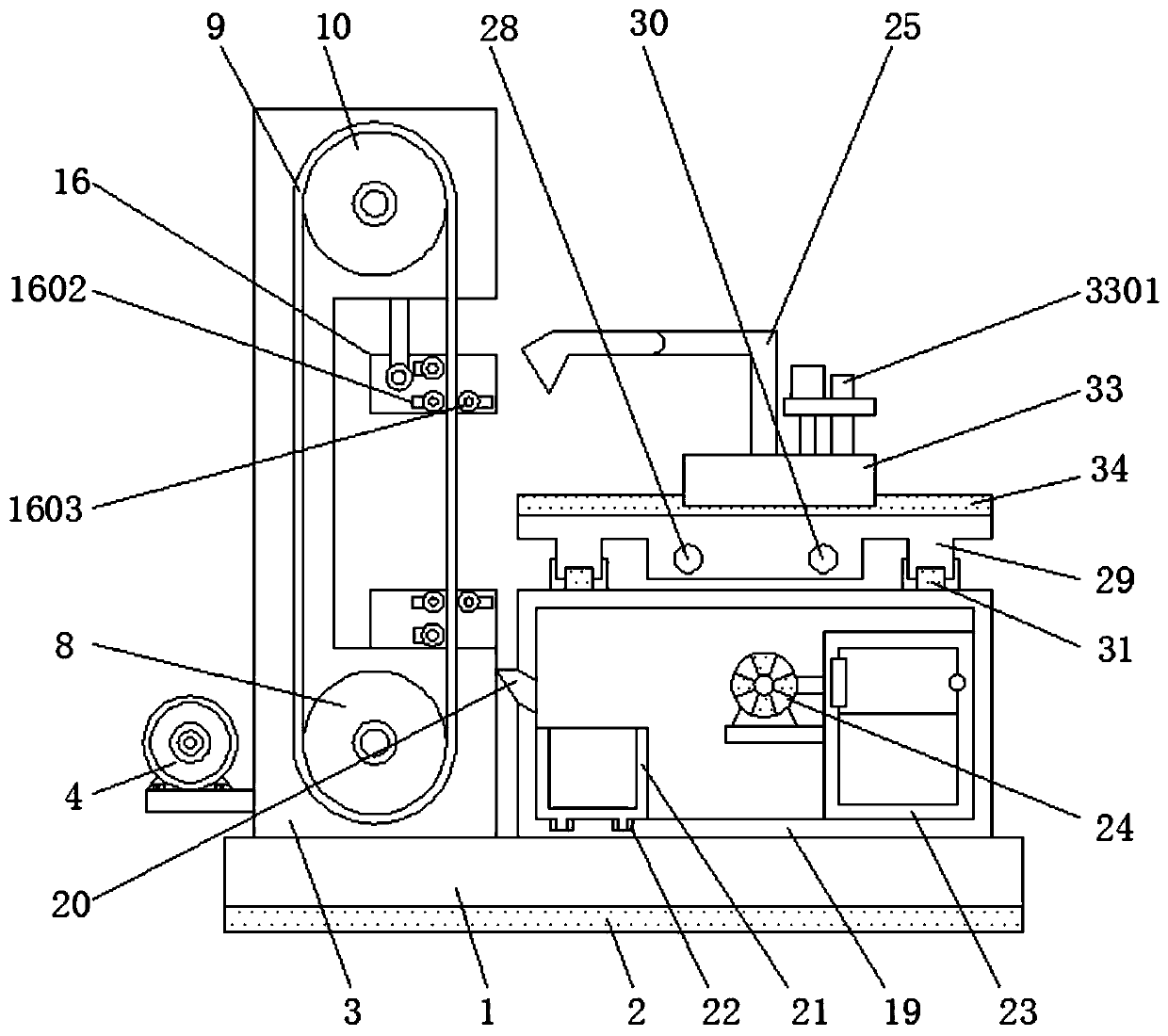
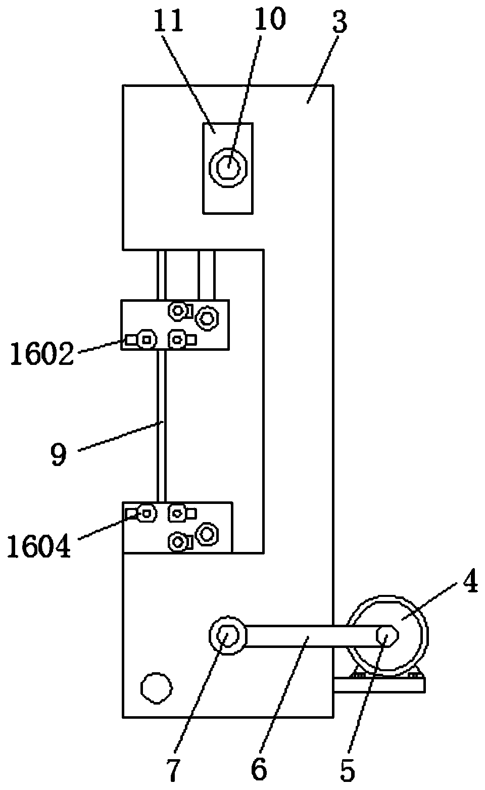
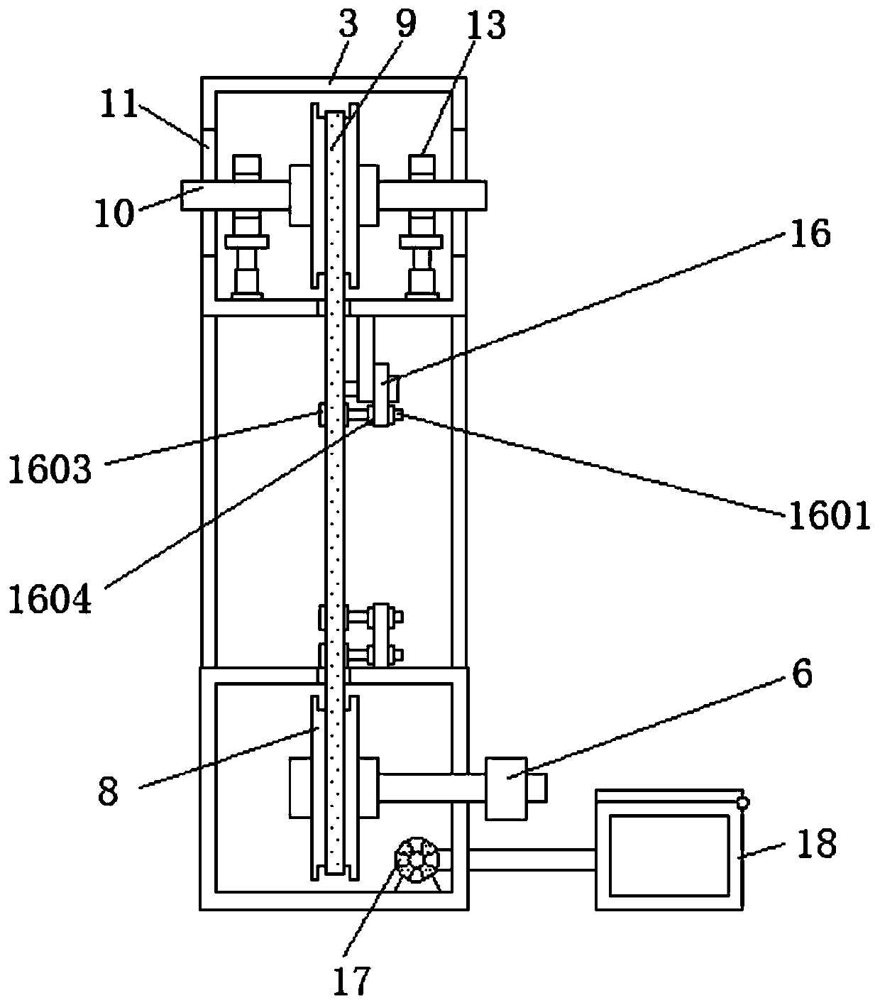
[0027] see Figure 1-6 , the present invention provides a technical solution: a digitally controlled band saw machine that is convenient for collecting dust, such as figure 1 , figure 2 with image 3 As shown, the lower end of the fixed seat 1 is provided with a shock absorber 2, and the upper surface of the fixed seat 1 is provided with an outer shell 3, and the left side of the outer shell 3 is provided with a first motor 4, and the first motor 4 and the ...


PUM


Abstract

The invention discloses a numerical control band-sawing machine facilitating dust collection. The numerical control band-sawing machine comprises a fixed seat, a positioning device, a machining tableand a second motor. A collecting box is arranged on the rear side of an outer shell, and the front side of the collecting box is connected with a first dust collector. A receiving tank is arranged onthe left side of the machining table, and the tail end of the receiving tank is arranged above the collecting box. The collecting box is connected with the internal bottom of the machining table through a sliding groove, and the sliding groove is formed in the internal bottom of the machining table. A second dust collector is connected with a dust colleting pipe, and the end, away from the seconddust collector, of the dust collecting pipe is arranged on the front side and the rear side of a band saw blade. According to the numerical control band-sawing machine facilitating dust collection, dust brought into the outer shell by the band saw blade can be discharged into the collecting box by the first dust collector, and it is avoided that the dust is accumulated in the outer shell for a long time to influence components in the outer shell; and in addition, by means of the arranged receiving tank, the dust falling onto the ground of a workshop in the sawing process can be reduced, and the dust can slide off into the collecting box through the receiving tank.

Description

technical field [0001] The invention relates to the technical field of numerically controlled band saw machines, in particular to a numerically controlled band saw machine which is convenient for dust collection. Background technique [0002] The CNC band saw machine is a mechanized processing equipment widely used in the processing of wood, glue, plexiglass, etc. It is mainly composed of a saw wheel and a band saw blade. On the wheel, the sawing of the workpiece is realized through the high-speed movement of the saw wheel under the driving motor. During the processing of common CNC band saw machines, a large amount of dust and waste will be generated, and the dust and waste will enter the band saw according to the band saw blade. In the housing, most of the accumulation falls on the surface of the CNC band saw machine, the workpiece fixing table and the workshop floor. A large amount of dust and waste is accumulated, which is difficult to clean up later, and the dust and wa...

Claims


Application Information

Patent Timeline
Patent Type & Authority Applications(China)
IPC IPC(8): B27B13/00B27B13/08B27B13/10B27B13/16B27B25/00B27B29/02B27G3/00B28D1/08B28D7/00B28D7/02B28D7/04B26D1/48B26D5/08B26D7/02B26D7/18B26D7/26
CPCB26D1/48B26D5/086B26D7/02B26D7/1863B26D7/2628B27B13/00B27B13/08B27B13/10B27B13/16B27B25/00B27B29/02B27G3/00B28D1/086B28D7/00B28D7/005B28D7/02B28D7/04
Inventor 孟建华
Owner 江苏东巨机械科技有限公司
Why Eureka
Try Eureka