Double-pipe type shield tail grouting device

A grouting device and shield tail technology, which is applied in the field of shield tunneling machines, can solve the problems of blockage of solidified substances, too much backflow slurry, and easy blockage of the grouting pipe, so as to improve the service life, strengthen the anti-blocking ability, and avoid the backflow of the slurry. Effect

Active Publication Date: 2020-02-18
中建八局轨道交通建设有限公司
View PDF6 Cites 1 Cited by
  • Summary
  • Abstract
  • Description
  • Claims
  • Application Information

AI Technical Summary

Problems solved by technology

Since the slurry containing cement and other components flows in the grouting pipeline, it is not only viscous but also solidified, so the grouting pipeline is easy to block after long-term use
On the other hand, the grouting pipeline is installed in the narrow space between the shield tail and the segment, and it is troublesome to clean and disassemble. In order to overcome this defect, the Chinese patent application No. 201210465719 "Grouting device and its use 》Provided a double-pipe shield tail grouting device, the specific idea is to set two grouting pipes at the shield tail grouting place, one for use and one for standby, and the spare grouting pipe can be used after the main pipeline is blocked; but in this patent The grouting device still has the following defects: 1. The operation of the shield machine is not continuous. When encountering special geological environments, shield machine maintenance, construction engineering changes, etc., the shield machine will suspend operations. At this time, the construction personnel need to Use the grouting pump to pump the inert grout into the grouting pipeline to avoid the solidification of the conventional grout in the grouting pipeline; in actual operation, the inert grout is fused with the conventional grout in the gap between the segment and the soil layer. Under the double influence of pressure and natural diffusion, it will flow back to the grouting pipeline, causing more solidified substances to be deposited on the inner wall of the grouting pipeline or even blockage; especially after the shield machine has been shut down for a long time, the gap between the segment and the soil The pressure of the pressure rises, and the return grout is more; the method of the prior art spare grouting pipe has no effect on the blockage of the grouting pipe caused by the backflow grout; For the grouting pipe, the plug is flushed away by the pressure of the grout; this design requires that the bonding force between the plug and the grouting pipe should not be too large, otherwise the grout will not be able to break the plug. However, the grout used in the shield machine is a viscous Fluid with high consistency and easy to solidify, and the pressure in the gap between the segment and the soil layer is high, there are many impurities such as stones, and the working conditions are very harsh. The ordinary plug inserted into the nozzle of the grouting pipe is easy to break Once the plug falls off, the grout will be poured into the spare grouting pipe, and the grout will solidify in a few hours, directly blocking the spare grouting pipe

Method used


Image

  • Double-pipe type shield tail grouting device
  • Double-pipe type shield tail grouting device
  • Double-pipe type shield tail grouting device

Examples


Embodiment 1

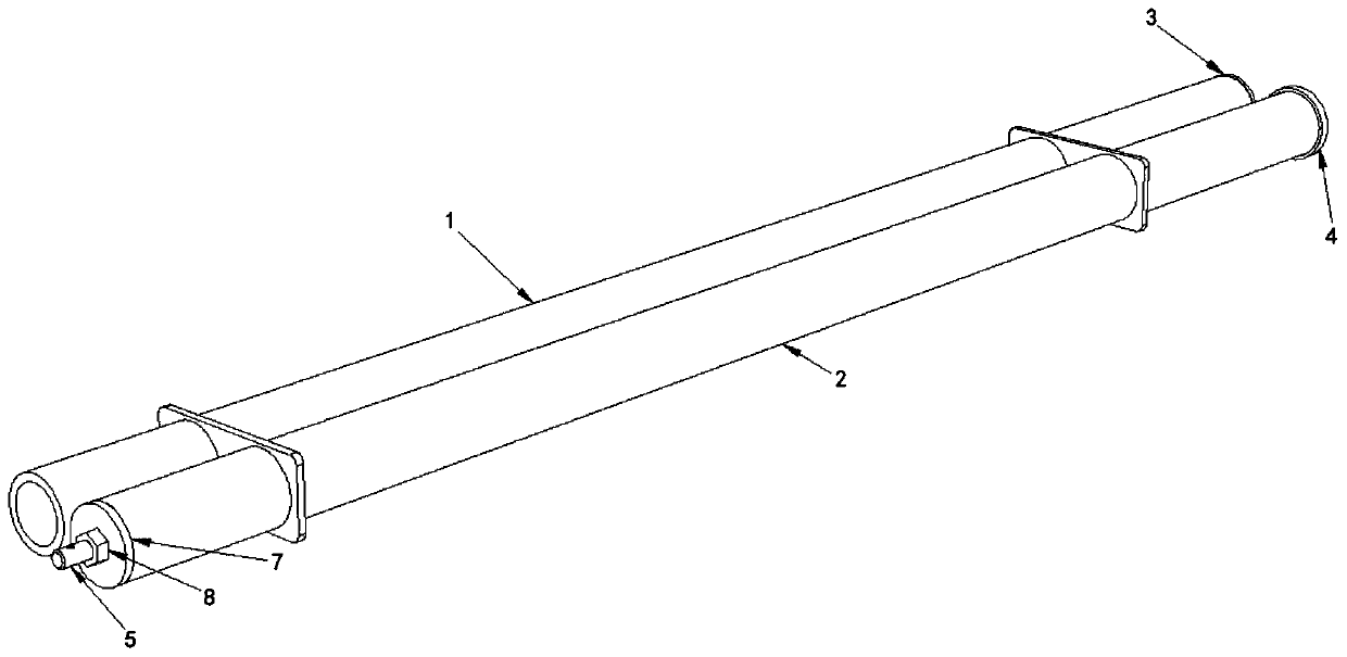
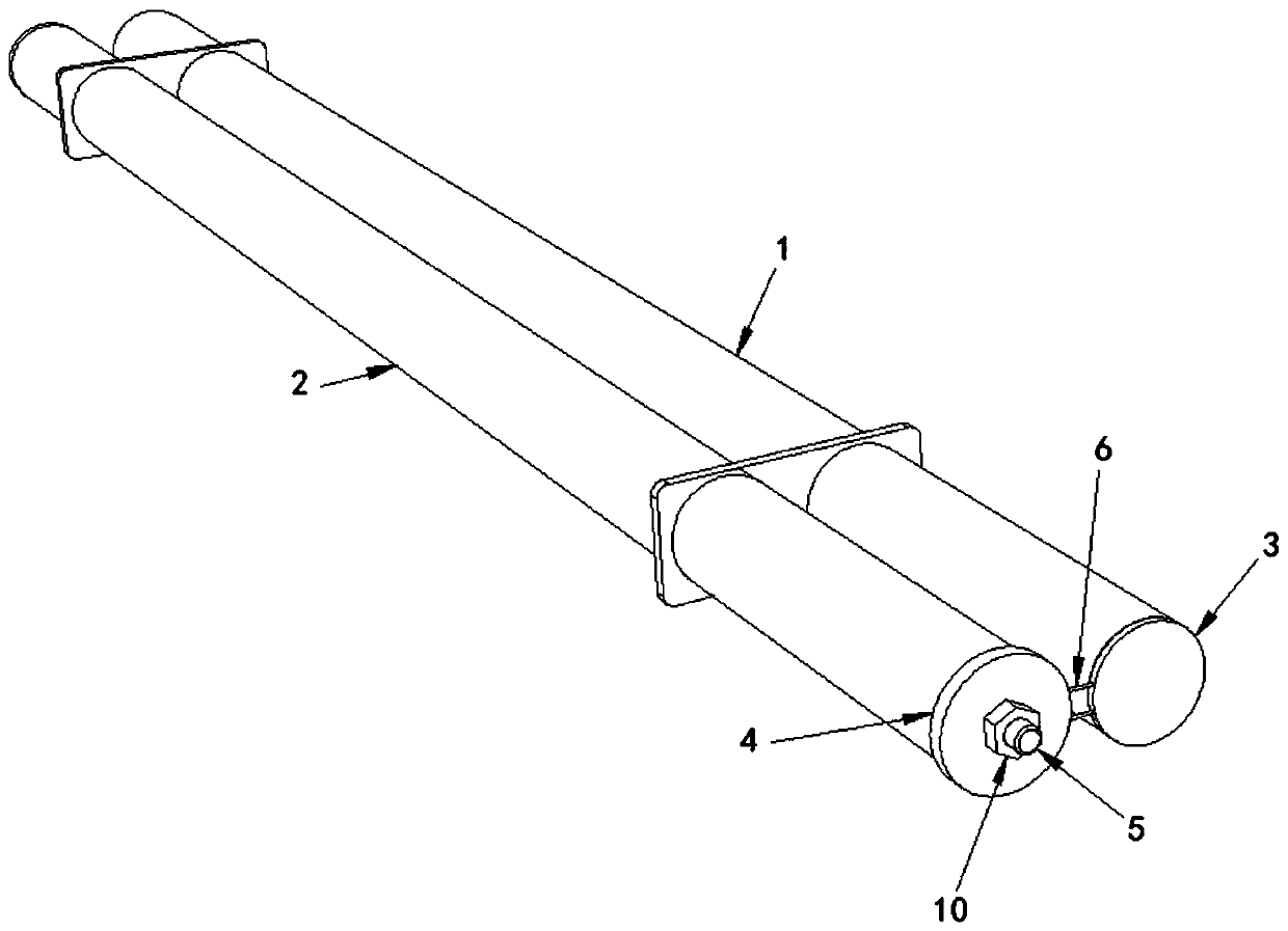
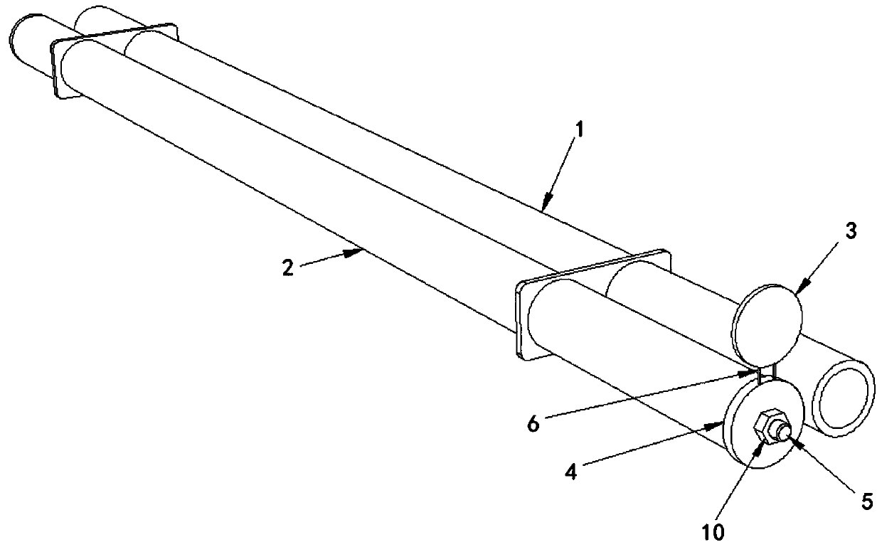
[0028] Such as Figure 1 to Figure 6 As shown, the double-tube shield tail grouting device in this embodiment includes a main pipe 1, a secondary pipe 2, a main end cover 3, an auxiliary end cover 4, a long rod 5 and a connecting rod 6;

[0029] The main pipe 1 and the auxiliary pipe 2 are parallel, and the main pipe 1 and the auxiliary pipe 2 are both cylindrical hollow pipes;

[0030] Such as Figure 4 As shown, the long rod 5 is located in the secondary pipe 2 and coaxial with the secondary pipe 2, the first end 501 of the long rod 5 exceeds the head of the secondary pipe 2, the first end 501 of the long rod 5 is provided with threads, and the long rod 5 is threaded. The first end 501 of the rod 5 is covered with a gasket 7 and a nut 8, and the diameter of the gasket 7 is not smaller than the outer diameter of the secondary pipe 2; the first end 501 of the long rod 5 is provided with a radial through hole 504;

[0031] The second end 502 of the long rod 5 is provided with...


PUM


Abstract

The invention discloses a double-pipe type shield tail grouting device. The device comprises a main pipe, an auxiliary pipe, a main end cover, an auxiliary end cover, a long rod and a connecting rod.The main pipe and the auxiliary pipe are both installed at the shield tail of a shield tunneling machine, and the main pipe and the auxiliary pipe are parallel. The auxiliary end cover covers the pipetail of the auxiliary pipe, the main end cover is coaxial with the main pipe, the two ends of the connecting rod are connected with the side face of the main end cover and the side face of the auxiliary end cover respectively, and the main end cover and the auxiliary end cover are located on the same plane. The long rod is located in the auxiliary pipe and is coaxial with the auxiliary pipe, a first end of the long rod goes beyond the pipe head of the auxiliary pipe, a second end of the long rod is fixedly connected with the auxiliary end cover, and the long rod can drive the auxiliary end cover to rotate. According to the double-pipe type shield tail grouting device, the long rod is arranged in the auxiliary pipe, and a constructor rotates the auxiliary end cover and the main end cover by using the long rod, so that the main end cover can be controlled to close the pipe tail of the main pipe, slurry is prevented from flowing back to the main pipe during shutdown of the shield tunneling machine, the main pipe has higher anti-blocking capability, and the service life of the main pipe is prolonged.

Description

technical field [0001] The invention relates to the field of shield machines, in particular to a double-pipe shield tail grouting device. Background technique [0002] The shield tail grouting device is used to synchronously inject grout into the gap between the segment and the soil layer during the operation of the shield machine. The shield tail grouting device in the prior art generally includes a grouting pump and a grouting pipeline, and the grouting pipe The road is installed at the end of the shield, and the end of the grouting pipeline points to the gap between the segment and the soil layer. Since the slurry containing cement and other components flows in the grouting pipeline, it is not only viscous but also can solidify, so the grouting pipeline is easily blocked after a long period of use. On the other hand, the grouting pipeline is installed in the narrow space between the shield tail and the segment, and it is troublesome to clean and disassemble. In order to ...

Claims


Application Information

Patent Timeline
Patent Type & Authority Applications(China)
IPC IPC(8): E21D11/10E21D9/06
CPCE21D9/0609E21D11/105
Inventor 吴浩凯朱湘旭王云鹏
Owner 中建八局轨道交通建设有限公司
Why Eureka
Try Eureka