Subway station prefabricated rail top air duct and installation mode thereof

A technology for rail top air ducts and subway stations, which is applied in earth square drilling, mine/tunnel ventilation, mining equipment, etc. It can solve problems such as difficult pouring, high maintenance costs, and unguaranteed airtightness, and achieves convenience. Transportation and hoisting, saving frame links, avoiding perishable and perishable effects

Pending Publication Date: 2020-02-18
JIANHUA CONSTR MATERIALS (JIANGSU) CO LTD
View PDF0 Cites 4 Cited by
  • Summary
  • Abstract
  • Description
  • Claims
  • Application Information

AI Technical Summary

Problems solved by technology

[0003] 1. Since the clearance height of the air duct on the rail top is generally less than 1 meter, it is very difficult to implement formwork erection and steel bar binding
[0004] 2. It is difficult to pour the hanging wall of the air duct on the top of the rail, and it is difficult to pour it densely. For the top-hung screen door, the positioning of the air duct civil construction is required to be controlled within 10mm. If the construction accuracy cannot be achieved, the rectification is particularly difficult
[0005] 3. After the construction of the main structure inside the station is completed, the second construction of the rail top air duct will be carried out, which requires the second entry of civil engineering. At the same time, electromechanical installation, station decoration and track construction will also enter the site. There will be cross operations, which will affect the construction period of the whole line
[0007] 1. The key connection nodes under permanent force are connected by steel structure, which has the problem of anti-corrosion and fire prevention, and the later maintenance cost is high
[0008] 2. The airtightness of the longitudinal connection is not considered in the prefabricated rail top air duct, and the airtightness cannot be guaranteed
[0009] 3. The components of the ordinary concrete prefabricated rail top air duct are too heavy and the construction is difficult
[0010] 4. Secondary civil work is still required, and construction efficiency has not improved
[0011] 5. It is necessary to drill holes in the middle plate to hang the prefabricated air duct for installation, and the construction accuracy is not high

Method used


Image

  • Subway station prefabricated rail top air duct and installation mode thereof
  • Subway station prefabricated rail top air duct and installation mode thereof
  • Subway station prefabricated rail top air duct and installation mode thereof

Examples


Embodiment 1

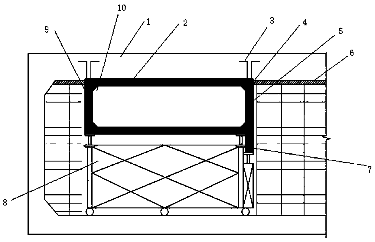
[0058] Such as figure 1 , figure 2 As shown, the lower end of the right air duct wall 5 is provided with a reserved hole 7, and two of the reserved holes 7 are arranged on the same horizontal line for installing the subway screen door. In the prior art, after pouring or installation of the rail-top air duct, when the screen door needs to be installed, holes are directly drilled on site, which is difficult to operate and easily destroys the stability of the installed structure.

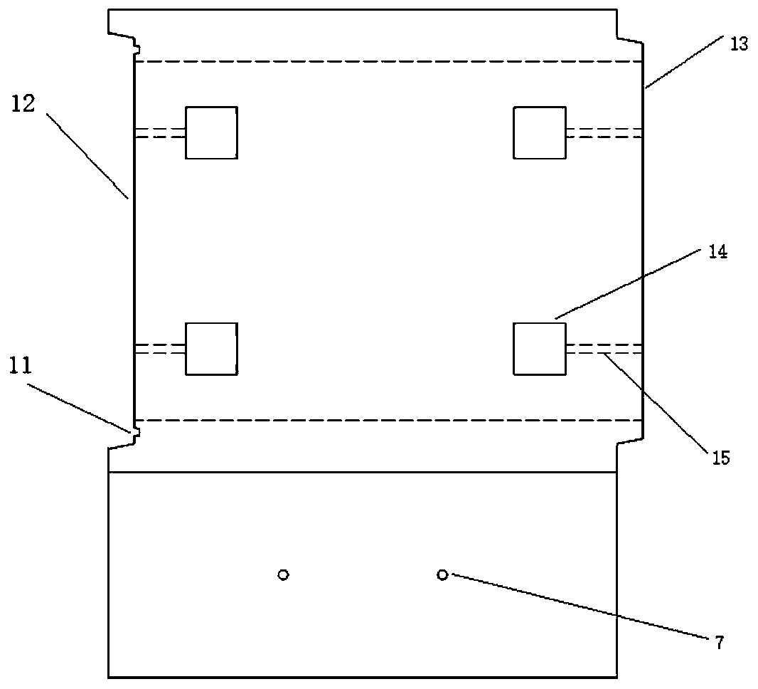
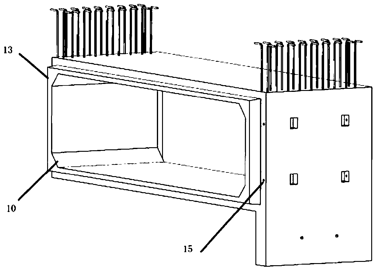
[0059] combine figure 2 , image 3 , Figure 4 It can be seen that the two ports of the left and right air duct walls are respectively provided with screw holes 15, and the outer surfaces of the left and right air duct walls are provided with hand holes 14, and the bolts can be put into the screw holes 15 through the hand holes 14 , the hand hole 14 is located about 15cm away from the port of the prefabricated rail top air duct, when the prefabricated rail top air ducts are connected to each othe...

Embodiment 2

[0075] Such as figure 1 , Figure 6 As shown, the lower end of the right air duct wall 5 is provided with a reserved hole 7, and two of the reserved holes 7 are arranged on the same horizontal line for installing the subway screen door. The reserved hole 7 is 190mm away from the lower end of the right air duct wall 5, and has a diameter of 20mm. In the prior art, after pouring or installation of the rail-top air duct, when the screen door needs to be installed, holes are directly drilled on site, which is difficult to operate and easily destroys the stability of the installed structure.

[0076] Such as Figure 6 , Figure 7 As shown, the ports on both sides of the left and right air duct walls are respectively provided with screw holes 15, and the outer surfaces of the left and right air duct walls are provided with hand holes 14, and the bolts can be put into the screw holes 15 through the hand holes 14. middle. Further, the hand hole 14 is composed of a pre-embedded st...


PUM


Abstract

The invention discloses a subway station prefabricated rail top air duct and an installation mode thereof, and belongs to the technical field of building engineering. The prefabricated rail top air duct is in a square shape and comprises left and right air duct walls, a top plate and a bottom plate, wherein the left and right air duct walls comprise the left air duct wall and the right air duct wall, and the upper end faces of the left air duct wall and the right air duct wall are both provided with horizontal reinforcing bars. According to the subway station prefabricated rail top air duct and the installation mode thereof, the prefabricated rail top air duct and a middle plate are anchored and connected by using the horizontal reinforcing bars extending outwards and cast-in-place concrete, the prefabricated rail top air duct and the middle plate are simultaneously constructed, so that secondary civil construction is not needed, the construction procedures are fewer, the constructionis more convenient, the construction efficiency is higher, the structural integrity is better, and meanwhile, the problem that a steel structure is prone to corrosion and prone to breakage due to explosion is solved. Furthermore, first grooves are reserved in the air duct walls, the top plate and the bottom plate in the longitudinal direction, seams is filled with rubber strips and sealing glue, bolt holes are reserved at the four ends of the air duct, pre-tightening force is provided through bolts during installation, two sections of air ducts are connected, and on the premise of meeting thesealing requirements, more safety and reliability are achieved.

Description

technical field [0001] The invention belongs to the technical field of construction engineering, and in particular relates to a prefabricated rail top air duct of a subway station and an installation method thereof. Background technique [0002] Nowadays, the construction of rail top air ducts in subway stations mainly adopts the traditional production method based on on-site construction. This production method has a low degree of industrialization, relatively extensive design and construction, unstable product quality, low construction efficiency, large labor demand, and material loss. The large amount of construction waste and resource and energy consumption cannot meet the sustainable development requirements of energy saving and environmental protection. In terms of construction, there are mainly the following shortcomings: [0003] 1. Since the clearance height of the air duct on the rail top is generally less than 1 meter, it is very difficult to implement formwork e...

Claims


Application Information

Patent Timeline
Patent Type & Authority Applications(China)
IPC IPC(8): E21F1/04
CPCE21F1/04
Inventor 李晟源黄美群贾英杰邓晓宇
Owner JIANHUA CONSTR MATERIALS (JIANGSU) CO LTD
Why Eureka
Try Eureka