
Anti-saturation radio frequency power amplifier

A radio frequency power and amplifier technology, applied in the field of radio frequency power amplifiers, can solve the problems of inability to meet communication standards, switching spectrum deterioration, etc., and achieve the effects of improving switching spectrum characteristics, improving performance, and working stably and reliably

Active Publication Date: 2020-02-18
RDA MICROELECTRONICS BEIJING
View PDF4 Cites 4 Cited by
  • Summary
  • Abstract
  • Description
  • Claims
  • Application Information

AI Technical Summary

Problems solved by technology

When the control voltage V ramp When it increases, the control loop approaches saturation, which will lead to a sharp deterioration of the switching spectrum, which cannot meet the requirements of communication standards

Method used


Image

  • Anti-saturation radio frequency power amplifier
  • Anti-saturation radio frequency power amplifier
  • Anti-saturation radio frequency power amplifier

Examples


Embodiment Construction

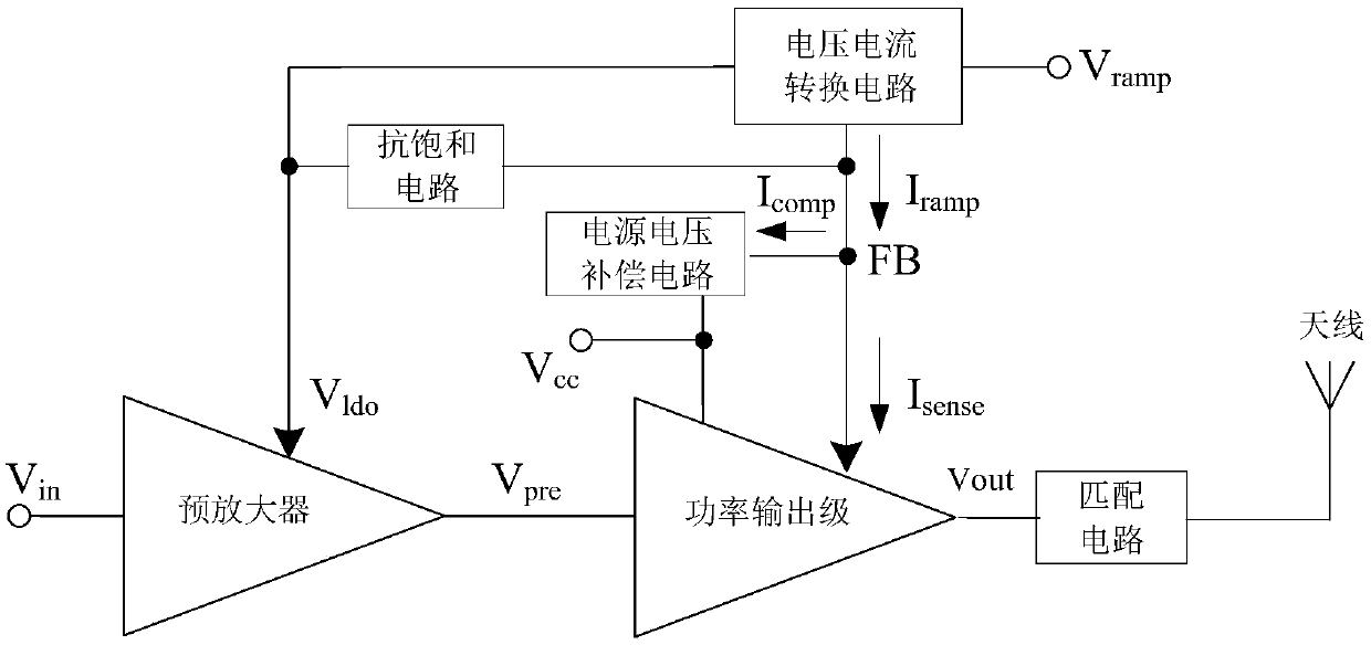
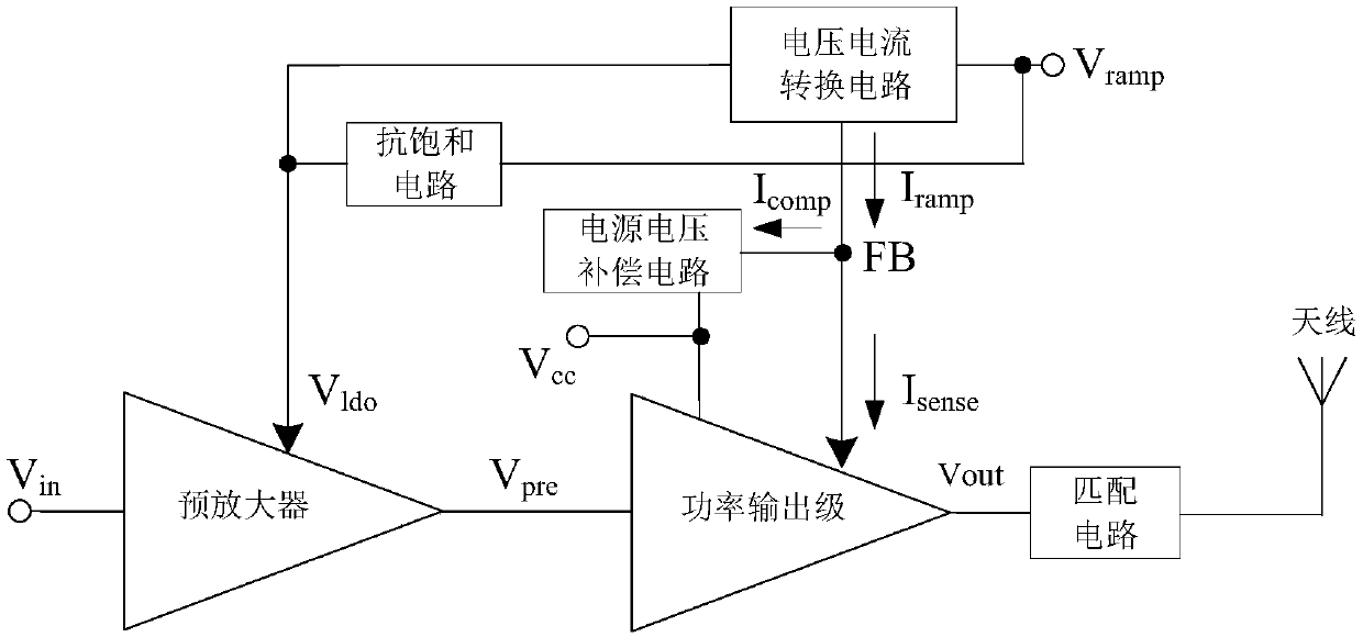
[0046] see figure 1 , Figure 1a , which is an embodiment of the anti-saturation radio frequency power amplifier provided by the present application. The anti-saturation radio frequency power amplifier shown in this embodiment includes a pre-amplifier, a power output stage, a voltage-to-current conversion circuit, a supply voltage compensation circuit and an anti-saturation circuit.

[0047] The pre-amplifier is used to convert the RF input signal V in Perform pre-amplification to obtain a larger dynamic range, and output a pre-amplified RF signal V pre .

[0048] The power output stage includes a power amplifier circuit and a current sampling circuit. The power amplifying circuit is used to control the voltage V ramp Under the control of the pre-amplified RF signal V pre Perform power amplification to obtain the output power V out . The output power V out After passing through the matching circuit, it is emitted by the antenna. The current sampling circuit is used t...


PUM


Abstract

The anti-saturation radio frequency power amplifier comprises a pre-amplifier, a power output stage, a voltage and current conversion circuit, a power supply voltage compensation circuit and an anti-saturation circuit. The voltage and current conversion circuit further comprises an operational amplifier, a low dropout regulator, a loop stabilization auxiliary circuit and a feedback circuit. The voltage and current conversion circuit is used for converting control voltage into reference current, the reference current is compared with sampling current of the power output stage through the operational amplifier, the comparison result is connected into the low dropout regulator, and the low dropout regulator provides power supply voltage for the preamplifier of the current working frequency band. The loop stabilization auxiliary circuit and the feedback circuit are introduced into the voltage and current conversion circuit to provide an additional negative feedback branch, so that the negative feedback current control loop in the whole PVT working interval of the radio frequency power amplifier can work stably and reliably.

Description

technical field [0001] This application relates to a radio frequency power amplifier in a mobile terminal, in particular to a radio frequency power amplifier including a power control circuit. Background technique [0002] In the mobile terminal, the RF power amplifier is used to amplify the power of the RF signal, and then feed it to the antenna for external transmission. During the communication process between the mobile terminal and the base station, due to the different distance between the two, or the antenna of the mobile terminal is blocked, etc., it is often necessary to perform power control on the transmit power output by the RF power amplifier in the mobile terminal. For example, a power control circuit is included in a radio frequency power amplifier for 2G (second generation mobile communication technology), and the power control circuit is controlled by the voltage V ramp Continuously control the output power of the RF power amplifier. [0003] In order to r...

Claims


Application Information

Patent Timeline
Patent Type & Authority Applications(China)
IPC IPC(8): H03F3/24H03F3/19
CPCH03F3/245H03F3/19Y02D30/70
Inventor 武振宇贾斌姚春琦
Owner RDA MICROELECTRONICS BEIJING
Learn More