
A Shaping and Forming Process for Adjusting the Outline Dimensions of the Tooth Parts of the Geared Shaft
A technology of shape size and molding process, which is applied in the field of plastic molding technology to achieve the effect of simple structure, high molding precision and improved work efficiency
- Summary
- Abstract
- Description
- Claims
- Application Information
AI Technical Summary
Problems solved by technology
Method used
Image

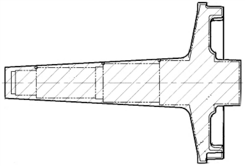
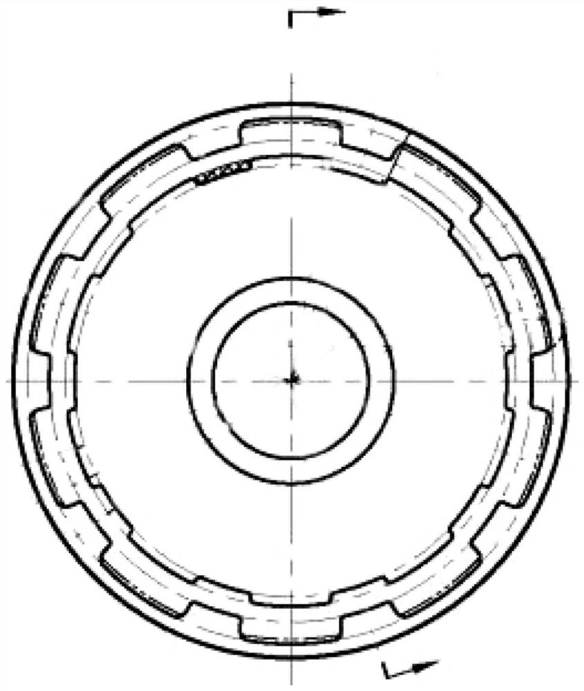
Examples
Embodiment
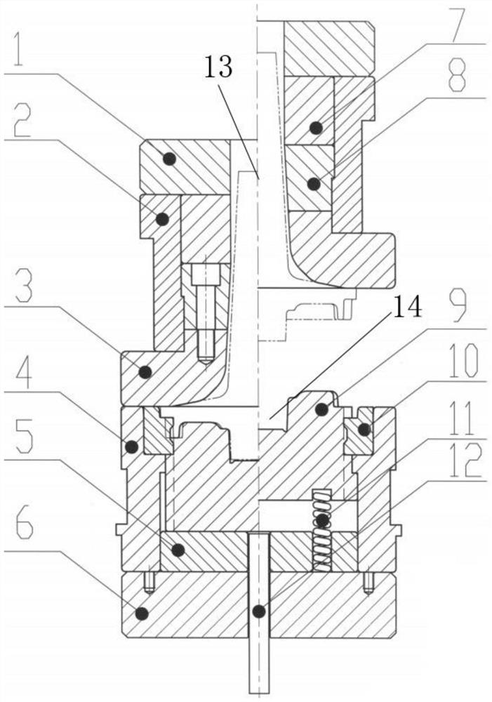
[0045] like image 3 The shaping and forming process for adjusting the external dimensions of the toothed part of the toothed shaft shown in the figure includes shaping the upper die shell pad 1, shaping the upper die shell 2, shaping the upper die core 2 3, shaping the lower die shell 4, shaping the lower die core pad 5. Lower backing plate 6, shaping upper die core pad 7, shaping upper die core 1 8, shaping lower die core 2 9, shaping lower die core blade 10, a set of Tama springs 11 and shaping lower die ejector pin 12, so The shaping upper mold shell backing plate 1, the shaping upper mold shell 2, the shaping lower mold shell 4 and the lower backing plate 6 are arranged in order from top to bottom. 8. The shaping upper die core 2 3, the shaping lower die core 2 9 and the shaping lower die core spacer 5 are arranged in order from top to bottom, and the shaping upper die core 2 3 is located in the shaping upper die shell 2 and the shaping lower die Between the shells 4, th...
PUM
 Abstract
Description
Claims
Application Information