Laser processing method and laser processing device

A laser processing method and laser processing technology, applied in metal processing equipment, laser welding equipment, manufacturing tools, etc., can solve the problems of processing accuracy and productivity reduction, and achieve the effect of suppressing the reduction of processing accuracy and productivity

Active Publication Date: 2020-02-21
PANASONIC INTELLECTUAL PROPERTY MANAGEMENT CO LTD
View PDF6 Cites 0 Cited by
  • Summary
  • Abstract
  • Description
  • Claims
  • Application Information

AI Technical Summary

Problems solved by technology

Therefore, at the boundary of the scanning range, there is a problem that the machining accuracy and productivity decrease due to the interface of machining traces, over machining or under machining.

Method used


Image

  • Laser processing method and laser processing device
  • Laser processing method and laser processing device
  • Laser processing method and laser processing device

Examples


Embodiment approach

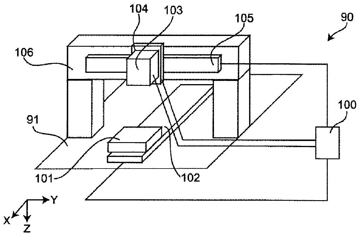
[0067] figure 1 It is a figure for the structure of the laser processing apparatus 90 which concerns on embodiment of this invention.

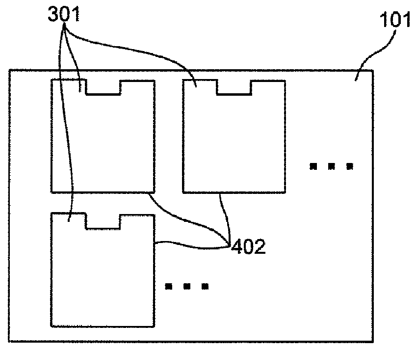
[0068] The laser processing method using the laser processing device 90 is to process the area (refer to Figure 4 The scanning trajectory 402 and the planned processing line 402a) of the scanning laser L are compared with the scanning area 401 of the scanning laser L (refer to Figure 4 ) A method of laser processing a large object 101 to be processed. Here, the scanning locus 402 is generated by scanning the laser light L, and the line on which the scanning locus 402 is generated is referred to as a line to be processed 402 a.

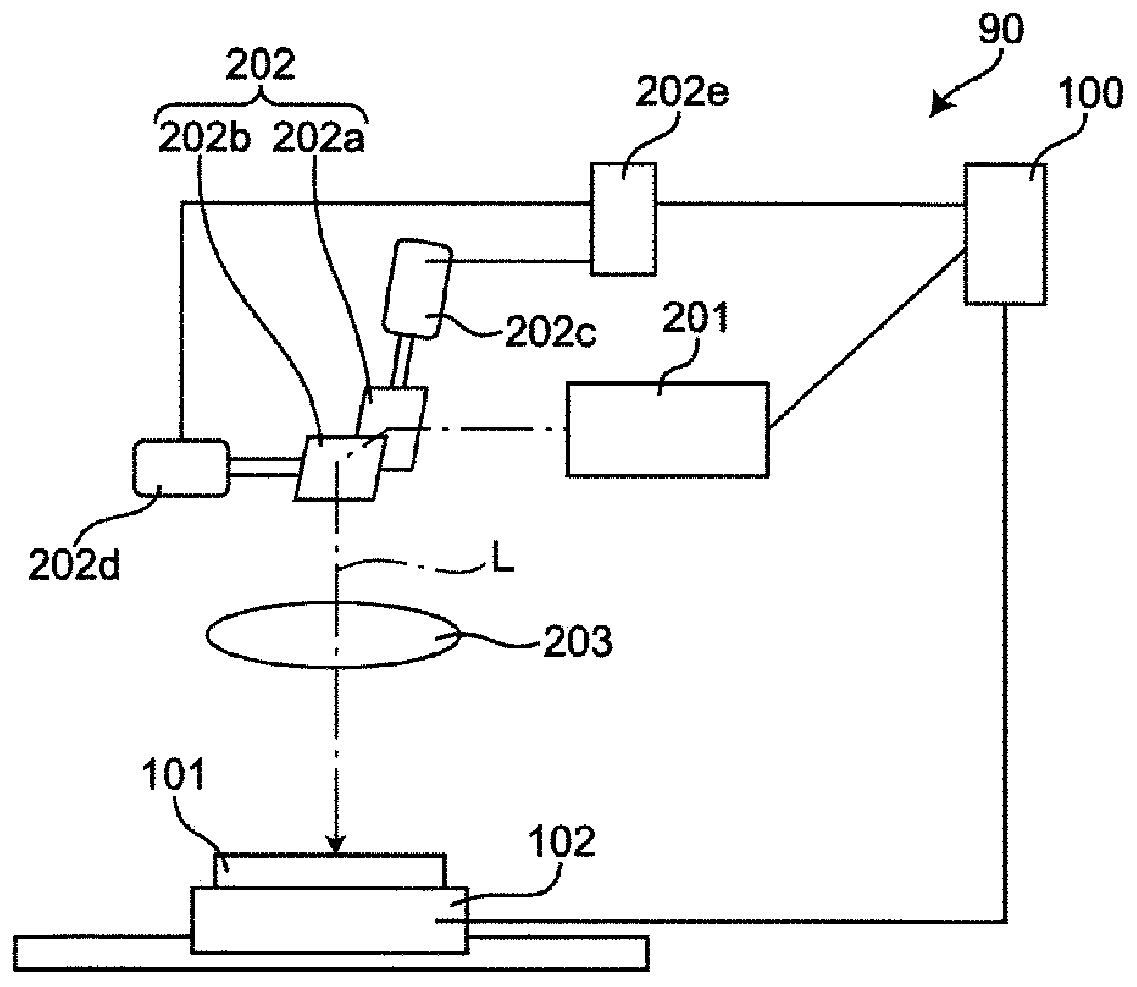
[0069] The laser processing device 90 includes at least: a driving table 102 for the object to be processed as an example of a first driving device, a laser emitting part, a galvano scanner (galvano scanner) 202, an fθ lens 203, and an example of a second driving device. The drive table and control unit 100 for sc...


PUM


Abstract

The present invention provides a laser processing method and a laser processing device, which can suppress a reduction in processing accuracy and productivity. An object to be processed is held on a drive table that moves in the first direction X. Then, the object to be processed is moved in the first direction by driving the table, and through a current detection scanner, laser L irradiating theobject to be processed from the current detection scanner and an ftheta lens are allowed to move for three or more than three times in the first direction and the opposite direction of the first direction on a part of same straight line of a processing predetermined line and then to be scanned relative to the object to the processed. The linear speed V0 of the scanning of the laser light is controlled in a relatively fixed manner. The linear velocity V0 in the departure scanning and return scanning is the difference between the departure scanning velocity Vs1 and the movement velocity Vt of the object to be processed and the difference between the return scanning velocity Vs2 and the movement velocity Vt. The moving speed Vt is equal to (Vs1-Vs2) / 2, the departure scanning speed Vs1 is greater than the return scanning speed Vs2, and the scanning speed Vs is greater than 2 * the moving speed Vt.

Description

technical field [0001] The present invention relates to a laser processing method and a laser processing device in laser cutting processing of an object to be processed such as a resin film. Background technique [0002] Processing methods and devices for cutting, drilling, and the like of various processing objects (that is, workpieces) by laser irradiation are known. [0003] The laser processing device is mainly composed of a driving table, a galvanometer scanner, a laser oscillator, and optical system components. Generally, the irradiated laser is passed through a condenser lens, and the focus position is focused on the workpiece to perform processing. In addition, in two-dimensional machining, there is a method of scanning an arbitrary trajectory with a table having a drive shaft or a galvano scanner. [0004] For example, there is a method of scanning laser light only by a galvano scanner. In this case, the scanning speed of the galvanometric scanner is high, so the ...

Claims


Application Information

Patent Timeline
Patent Type & Authority Applications(China)
IPC IPC(8): B23K26/36B23K26/08B23K26/082
CPCB23K26/36B23K26/082B23K26/083
Inventor 恒吉拓央川西努小林勇治冈田敏幸木田胜启
Owner PANASONIC INTELLECTUAL PROPERTY MANAGEMENT CO LTD
Why Eureka
Try Eureka