Engine cylinder sleeve dismounting device

A technology for engine cylinders and dismantling devices, which is applied in hand-held tools and manufacturing tools, etc. It can solve problems such as increased friction of cylinder liners, scratches on cylinder head mounting surfaces, and large screws, so as to improve centering deviation and avoid screw threads Effects of damage and large transmission torque

Inactive Publication Date: 2020-02-21
NO 711 RES INST CHINA SHIPPING HEAVY IND GRP
View PDF8 Cites 3 Cited by
  • Summary
  • Abstract
  • Description
  • Claims
  • Application Information

AI Technical Summary

Problems solved by technology

[0004] 1. Some engine cylinder liner removal devices can only be used to remove cylinder liners of in-line engines, and cannot remove cylinder liners of V-type engines;
[0005] 2. Although the individual engine cylinder liner removal device can be used to remove the cylinder liner of the V-type engine, but because its load-bearing bracket is placed on the cylinder head installation surface of the V-type engine body and lacks positioning, and the cylinder head installation surface has an inclination angle, Therefore, the load-bearing bracket can slide, which can easily cause scratches on the cylinder head mounting surface;
[0006] 3. After the engine has been used for a long time, there are impurities such as scale between the cylinder liner and the body, which increases the friction when pulling the cylinder liner. The existing engine cylinder liner removal device mainly relies on the screw to bear the force, and the screw bears a large pulling force. Cause the threaded part of the screw to be easily strained or even fail

Method used


Image

  • Engine cylinder sleeve dismounting device
  • Engine cylinder sleeve dismounting device
  • Engine cylinder sleeve dismounting device

Examples


Embodiment Construction

[0030] The present invention will be described in detail below in conjunction with the accompanying drawings and specific embodiments.

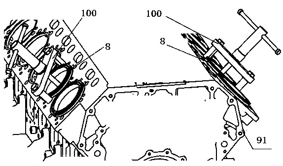
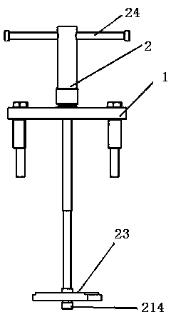
[0031] Figure 1 to Figure 11 Shown is the structure of an engine cylinder liner removal device according to an embodiment of the present invention. see Figure 1 to Figure 11 , according to an embodiment of the present invention, an engine cylinder liner removal device 100 includes a bracket assembly 1 and a pulling assembly 2 .

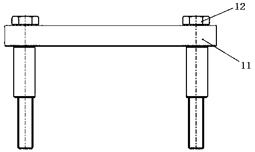
[0032] The bracket assembly 1 plays the role of bearing and positioning, which includes a bracket 11 and a pair of mounting bolts 12 , the bracket 11 can be connected with a pair of cylinder head bolt holes 912 on the body 91 of the engine through a pair of mounting bolts 12 . The bracket 11 includes a top plate 111 and a pair of uprights 112 , the upper ends of the pair of uprights 112 are welded to the bottom of the top plate 111 . Each column 112 has a bolt installation through hole 113 extending along the he...


PUM


Abstract

The invention provides an engine cylinder sleeve dismounting device which comprises a bracket assembly and a drawing assembly, wherein the bracket assembly comprises a bracket and a plurality of mounting bolts; the bracket can be connected with a cylinder cover bolted hole on a body through the mounting bolts; the drawing assembly comprises a spiral driving mechanism and a pulling plate; the spiral driving mechanism comprises a driving rod and a rotating component; the driving rod penetrates through the bracket; the upper end of the driving rod is engaged with the rotating component; the lowerend of the driving rod is connected with the pulling plate; the pulling plate can be propped against the lower end of the engine cylinder sleeve to be dismounted; the rotating component and the bracket can relatively rotate and not move downwards; and the rotating component can rotate under the action of an external force to further drive the driving rod and the pulling plate to move upwards. A cylinder sleeve can be drawn out from a line engine and a V-type engine, the operation is simple, and a cylinder cover mounting surface of the engine body cannot be scratched when the engine cylinder sleeve dismounting device.

Description

technical field [0001] The invention relates to engine overhaul tooling. Background technique [0002] The cylinder liner is an important part of the engine cylinder unit. The cylinder liner is installed in the cylinder liner hole of the engine body. It forms a closed space together with the cylinder head, piston and piston ring. The volume of the closed space is called the cylinder volume of the engine. During the working process of the engine, the cylinder liner needs to withstand the explosive pressure of combustible gas, the inner surface is subjected to the reciprocating friction of the piston ring group, and the outer surface is washed by cooling water. The harsh working environment will have an important impact on the working life of the cylinder liner. influences. When the inner surface of the cylinder liner is greatly worn, cavitation occurs on the outer surface, or there is a scratch between the cylinder liner and the piston skirt, or a cylinder failure, etc., th...

Claims


Application Information

Patent Timeline
Patent Type & Authority Applications(China)
IPC IPC(8): B25B27/02
CPCB25B27/023
Inventor 王维东徐彦黄锦川林琳殷筱徐俊
Owner NO 711 RES INST CHINA SHIPPING HEAVY IND GRP
Why Eureka
Try Eureka