Eureka AIR delivers breakthrough ideas for toughest innovation challenges, trusted by R&D personnel around the world.

Wave type material mixing mechanism for plastic machining

A wave type and mixing technology, applied in the field of plastic processing, can solve the problems of inconvenient feeding, blockage of feeding pipes, and less contact area, and achieve the effect of avoiding plastic splashing and facilitating feeding.

Active Publication Date: 2020-02-21
广东光塑科技股份有限公司
View PDF4 Cites 4 Cited by
  • Summary
  • Abstract
  • Description
  • Claims
  • Application Information

AI Technical Summary

Problems solved by technology

[0003] However, when currently mixing wet granular plastics, the wet granular plastics are directly poured into the inside of the mixing tank for mixing. The volume of the mixing tank is relatively small. The contact area of ​​wet granular materials is small, and it is easy to form stratification during mixing, resulting in uneven mixing of plastics and affecting the processing of plastics; and the granular plastics that pass through the mixing tank pass through the tubular feeding pipe during feeding, with wet Granular plastic is easy to stick to the feeding pipe, causing the feeding pipe to be blocked and affecting the feeding speed; and when feeding into the mixing tank, it is always fed at the top of the mixing tank, and the materials added to the mixing tank are piled up together. It is convenient to load materials, and it is not convenient to stir the plastic

Method used


Image

  • Wave type material mixing mechanism for plastic machining
  • Wave type material mixing mechanism for plastic machining
  • Wave type material mixing mechanism for plastic machining

Examples


Embodiment Construction

[0026] In order to make the technical means, creative features, goals and effects achieved by the present invention easy to understand, the present invention will be further described below in conjunction with specific embodiments.

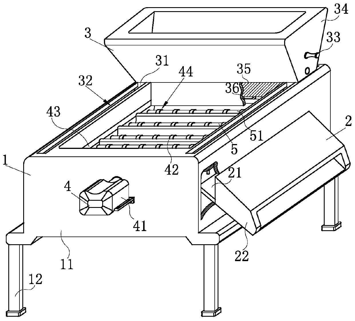
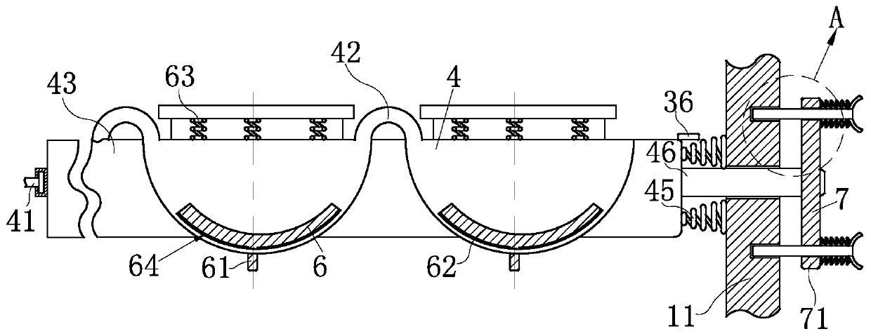
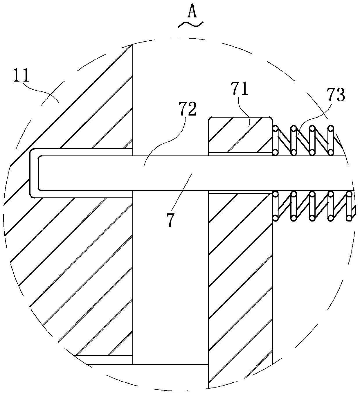
[0027] Such as Figure 1-Figure 8 As shown, a plastic processing wave mixing mechanism according to the present invention includes a supporting mechanism 1, a feeding mechanism 2, a feeding mechanism 3, a mixing mechanism 4, a stirring mechanism 5, a control mechanism 6 and a limit mechanism 7 The top of the supporting mechanism 1 used to support the overall mechanism is equipped with the mixing mechanism 4 for mixing plastics, and one end of the mixing mechanism 4 is installed with the supporting mechanism 1. The position-limiting mechanism 7 that is slidably connected between them, the top of the support mechanism 1 is slidably connected with the feeding mechanism 3, and the side wall of the feeding mechanism 3 is equipped with the control mecha...


PUM


Abstract

The invention relates to the field of plastic machining, in particular to a wave type material mixing mechanism for plastic machining. The wave type material mixing mechanism comprises a supporting mechanism, a discharging mechanism, a feeding mechanism, a material mixing mechanism, a stirring mechanism, a control mechanism and a limiting mechanism. The top of a box body is connected with the feeding mechanism in a sliding manner. The material mixing mechanism abutting against the feeding mechanism is connected in the box body in a sliding manner. After plastic particles are fully injected into the feeding mechanism, a handle is pushed to make the feeding mechanism abut against material mixing plates of a wave-shaped structure, and furthermore, inner plastic located in the feeding mechanism evenly fall on the surface of the material mixing mechanism. The feeding mechanism abuts against the material mixing mechanism when feeding is not conducted, and the phenomenon that the material mixing mechanism rotates, and plastic is spilled is avoided. The limiting mechanism is connected with the box body in a sliding manner during material mixing and is matched with the feeding mechanism tolimit the material mixing mechanism, the material mixing mechanism is prevented from inclining, the limiting mechanism is pulled to get away from the box body during discharging, the limiting mechanism is separated from the box body and does not limit the material mixing mechanism any more, and discharging is facilitated.

Description

technical field [0001] The invention relates to the field of plastic processing, in particular to a wave-type mixing mechanism for plastic processing. Background technique [0002] Plastic is a high molecular compound polymerized by addition polymerization or polycondensation reaction with monomer as raw material. It has medium resistance to deformation and is between fiber and rubber. The main component of plastic is resin, and resin refers to a polymer compound that has not been mixed with various additives. [0003] However, when currently mixing wet granular plastics, the wet granular plastics are directly poured into the inside of the mixing tank for mixing. The volume of the mixing tank is relatively small. The contact area of ​​wet granular materials is small, and it is easy to form stratification during mixing, resulting in uneven mixing of plastics and affecting the processing of plastics; and the granular plastics that pass through the mixing tank pass through the...

Claims


Application Information

Patent Timeline
Patent Type & Authority Applications(China)
IPC IPC(8): B29B7/08B29B7/22B29B7/26B29B7/24B29B7/28B29B7/74
CPCB29B7/08B29B7/26B29B7/24B29B7/06B29B7/00
Inventor 李杰
Owner 广东光塑科技股份有限公司
Why Eureka
Eureka Blog
Learn More