Power transmission system of hybrid electric vehicle and hybrid electric vehicle
What is Al technical title?
Al technical title is built by PatSnap Al team. It summarizes the technical point description of the patent document.
A hybrid vehicle and power transmission technology, which is applied to the layout of multiple different prime movers of hybrid vehicles, electric braking systems, and general power plants, and can solve the problem of high limit power requirements, inability to guarantee engines, low efficiency, etc. Problems, to achieve excellent power, improve life, improve the effect of economy
Active Publication Date: 2020-12-08
GUANGZHOU AUTOMOBILE GROUP CO LTD
View PDF11 Cites 0 Cited by
Summary
Abstract
Description
Claims
Application Information
AI Technical Summary
This helps you quickly interpret patents by identifying the three key elements:
Problems solved by technology
Method used
Benefits of technology
Problems solved by technology
In the series mode, there is no mechanical connection between the engine and the output shaft, which can realize the optimal control of the speed / torque, but all its energy needs to be transferred to the output shaft after two conversions between mechanical power and electric power, and the loss is relatively large ;Parallel transmission has high efficiency, but the mechanical connection between the engine and the output shaft cannot ensure that the engine is always in a better working area, and is usually used for medium and high speeds; the hybrid combination combines the advantages of series and parallel, which can not only realize the optimization of the engine control, and can achieve high-efficiency control at medium and high speeds, but the limit power requirements of the motor are high when the vehicle starts, and the efficiency is low
Method used
Image
Click on the blue label to locate the original text in one second.
Reading with bidirectional positioning of images and text.
Examples
Embodiment Construction
[0076] In order to further explain the technical means and effects of the present invention to achieve the intended purpose of the invention, the specific implementation, structure, features and effects of the present invention will be described in detail below in conjunction with the accompanying drawings and examples.
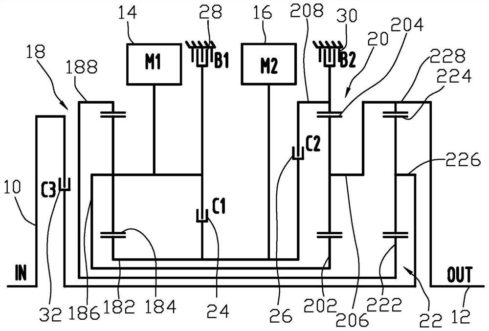
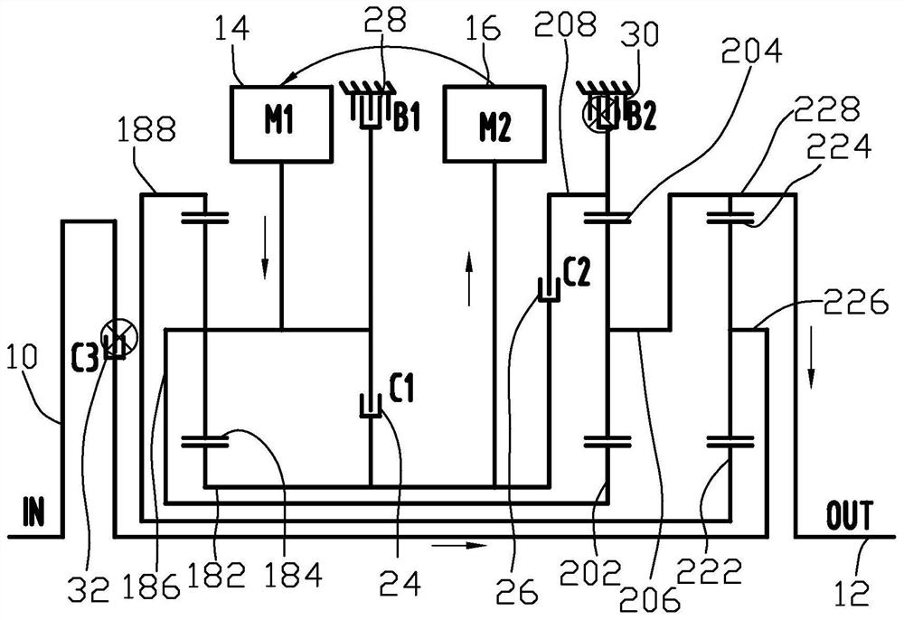
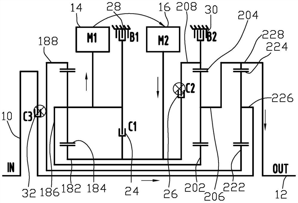
[0077] Such as figure 1 As shown, an embodiment of the present invention provides a power transmission system of a hybrid vehicle, including an input element 10 connected to an output shaft of an engine, an output element 12, a first electric motor 14, a second electric motor 16, and a first planetary gear mechanism 18 , the second planetary gear mechanism 20 , the third planetary gear mechanism 22 , the first clutch 24 , the second clutch 26 , the first brake 28 and the second brake 30 .
[0078] The first planetary gear mechanism 18 includes a first sun gear 182, a first planet gear 184, a first planet carrier 186 and a first ring gear 188, the first planet...
PUM
Abstract
The invention discloses a power transmission system of a hybrid vehicle and the hybrid vehicle. The power transmission system comprises a first planetary gear mechanism, a second planetary gear mechanism, a third planetary gear mechanism, an input member, an output member, a first motor, a second motor, a first clutch, a second clutch, a first brake and a second brake, wherein the input member isconnected to a third planet carrier, the output member is connected to a third gear ring, a first planet carrier is fixedly connected with a rotor of the first motor, a first sun gear is fixedly connected with a rotor of the second motor, the first clutch is connected between the first sun gear and a first brake, the second clutch is connected between the first sun gear and a second gear ring, thefirst planet carrier is connected with the first brake, one end of the second brake is connected with the second gear ring, the first planet carrier and a second sun gear are fixedly connected, a first gear ring and a third sun gear are fixedly connected, and a second planet carrier and a third gear ring are fixedly connected. According to the power transmission system, through reasonable layoutof planetary rows, various working modes are achieved, the performance of a gearbox system is improved, and higher transmission efficiency is further obtained.
Description
technical field [0001] The invention relates to the technical field of hybrid vehicles, in particular to a power transmission system of a hybrid vehicle and the hybrid vehicle. Background technique [0002] With the increasingly stringent environmental protection measures around the world, hybrid vehicles have become a focus of automobile research and development because of their energy-saving and low-emission characteristics. Under the current technical level and application conditions, the hybrid electric vehicle is the most industrialized and marketable model among the electric vehicles. A hybrid vehicle uses an internal combustion engine and an electric motor as a hybrid power source. It not only has the advantages of good fuel engine power, quick response and long working time, but also has the benefits of no pollution and low noise from the electric motor, achieving the best match between the engine and the electric motor. . [0003] At present, the driving system of...
Claims
Application Information
Patent Timeline
Application Date:The date an application was filed.
Publication Date:The date a patent or application was officially published.
First Publication Date:The earliest publication date of a patent with the same application number.
Issue Date:Publication date of the patent grant document.
PCT Entry Date:The Entry date of PCT National Phase.
Estimated Expiry Date:The statutory expiry date of a patent right according to the Patent Law, and it is the longest term of protection that the patent right can achieve without the termination of the patent right due to other reasons(Term extension factor has been taken into account ).
Invalid Date:Actual expiry date is based on effective date or publication date of legal transaction data of invalid patent.