A method for identifying the balance pole curve of twin-engine aircraft through ground taxiing test

A technology of ground taxiing and taxiing test, applied in the direction of aircraft component testing, etc., can solve the problems of high risk and high cost of air flight test, and achieve the effect of shortening the cycle, reducing the risk of flight test, and saving costs.

Active Publication Date: 2022-04-08
CHENGDU AIRCRAFT INDUSTRY GROUP
View PDF17 Cites 0 Cited by
  • Summary
  • Abstract
  • Description
  • Claims
  • Application Information

AI Technical Summary

Problems solved by technology

[0008] 3) Air flight tests are expensive and risky;

Method used


Image

  • A method for identifying the balance pole curve of twin-engine aircraft through ground taxiing test
  • A method for identifying the balance pole curve of twin-engine aircraft through ground taxiing test
  • A method for identifying the balance pole curve of twin-engine aircraft through ground taxiing test

Examples


Embodiment 1

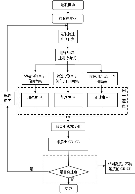
[0076] A method of identifying the balance pole curve of a twin-engine aircraft through ground taxiing tests, ignoring the change in intake distortion caused by engine speed changes; the test runway is horizontal, and the angle of attack and pitch angle are the same; figure 1 As shown in Fig. 1, select two sliding state points with different pitch angles to carry out the sliding tests of synchronous acceleration / deceleration and asynchronous acceleration / deceleration of the two engines at different speeds, respectively, and calculate the acceleration / deceleration through the acceleration / deceleration motion graph; thus The model resistance and lift-induced resistance factors are calculated, such as Figure 9 As shown, the fitted plane balance pole curve CD-CL. In order to facilitate the calculation of the correction amount of the aircraft balance pole curve, two taxiing state points with different pitch angles are selected for testing.

[0077] The invention overcomes the in...

Embodiment 2

[0079] This embodiment is optimized on the basis of embodiment 1, such as figure 1 Shown, the present invention comprises the following steps:

[0080] 1) Select working conditions, namely weight, speed and pitch angle;

[0081] 2) Under two different pitch angles, the sliding tests of the synchronous acceleration / deceleration of the two engines at different speeds and the asynchronous acceleration / deceleration of the two engines are carried out;

[0082] 3) Calculate the acceleration / deceleration in the same speed range during different taxiing processes;

[0083] 4) Through the taxiing process in different states, the drag coefficient, lift-induced drag factor and form resistance are respectively solved, and the aircraft equilibrium pole curve under this working condition (speed point) is identified;

[0084] 5) Change the speed, repeat steps 2) to 4), and identify the balance pole curves of the aircraft at different speeds.

[0085] As shown in Table 1, two state points...

Embodiment 3

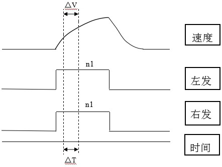
[0091] This embodiment is optimized on the basis of embodiment 1 or 2, as figure 2 As shown, the calculation formula of the acceleration / deceleration motion in the sliding test is as follows:

[0092]

[0093] in, L is the lift of the aircraft, N is the supporting force of the aircraft tire, G is the gravity of the aircraft, T is the total thrust of the two engines, D is the drag of the aircraft, f is the friction force on the plane, m for the mass of the aircraft, a is the acceleration / deceleration of the aircraft, ρ is the density, V for speed, S is the reference area, CL is the lift coefficient, cd is the drag coefficient.

[0094] Other parts of this embodiment are the same as those of Embodiment 1 or 2 above, so details are not repeated here.


PUM


Abstract

The invention discloses a method for identifying the balance polar curve of a twin-engine aircraft through a ground taxiing test, ignoring the variation of the intake distortion caused by the change of the engine speed; the test runway is horizontal, and the angle of attack and pitch angle are the same; two The sliding state points of different pitch angles are respectively subjected to the sliding test of synchronous acceleration / deceleration and asynchronous acceleration / deceleration of the twin engines at different speeds, and the acceleration / deceleration speed is calculated by the acceleration / deceleration motion graph; thus the shape resistance and lift The resulting drag factor is fitted to obtain the balance pole curve of the aircraft CD‑CL . The invention overcomes the inaccuracy of the engine bench test data, obtains the balance polar curve of the real aircraft, and at the same time saves the cost of the air flight test and reduces the risk of the first flight test. The invention identifies the balance polar curve of the aircraft on the basis of not using the test data of the engine bench, and establishes a basis for the rational formulation of the follow-up first flight test plan, and has better practicability.

Description

technical field [0001] The invention belongs to the technical field of aircraft testing, and in particular relates to a method for identifying the balance pole curve of a twin-engine aircraft through a ground taxiing test. Background technique [0002] At present, the known balance pole curve data of the aircraft are obtained through wind tunnel tests, and some corrections are made to the test data. The wind tunnel test is to obtain the aerodynamic characteristics of the real aircraft after the aerodynamic characteristics of the wind tunnel model are corrected. This requires similarity, interference correction and other links. Therefore, it is still difficult to obtain the aerodynamic parameters of the real aircraft. There are relatively mature methods for hole wall interference correction and Reynolds number correction for test data, but the accuracy of the correction results still needs to be further improved. [0003] In addition, due to the influence of factors such as ...

Claims


Application Information

Patent Timeline
Patent Type & Authority Patents(China)
IPC IPC(8): B64F5/60
CPCB64F5/60
Inventor 冯宇鹏李锐李阳周伟
Owner CHENGDU AIRCRAFT INDUSTRY GROUP
Why Eureka
Try Eureka