Automatic filling machine for beverage bottles

An automatic feeding and beverage bottle technology, applied in the directions of bottling machines, packaging, synchronizing devices, etc., can solve the problems of increasing the difficulty of the turntable and the beverage bottle conveying line, increasing the difficulty of the turntable, increasing the cost of the turntable, etc., and achieves ingenious structural design. , the structure is simple, the effect of saving the cost of the structure

Inactive Publication Date: 2020-02-21
DONGGUAN RONGGONG AUTOMATION TECH CO LTD
View PDF2 Cites 4 Cited by
  • Summary
  • Abstract
  • Description
  • Claims
  • Application Information

AI Technical Summary

Problems solved by technology

[0007] Most of the existing beverage filling machines include beverage bottle conveying and liquid injection devices installed on the beverage bottle conveying line. Most of the existing liquid injecting devices directly inject liquid into the beverage bottles on the conveying line. Some use a turntable to realize the multi-station injection of multiple beverage bottles at different times, but the beverage bottles may be centrifuged during the rotation process. This will increase the difficulty of making the turntable, and at the same time increase the cost of the turntable, and it will also increase the difficulty of the turntable and beverage bottle conveying line

Method used


Image

  • Automatic filling machine for beverage bottles
  • Automatic filling machine for beverage bottles
  • Automatic filling machine for beverage bottles

Examples


Embodiment Construction

[0033] In order to enable those skilled in the art to better understand the technical solution of the present invention, the present invention will be described in detail below in conjunction with the accompanying drawings. The description in this part is only exemplary and explanatory, and should not have any limiting effect on the protection scope of the present invention. .

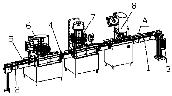
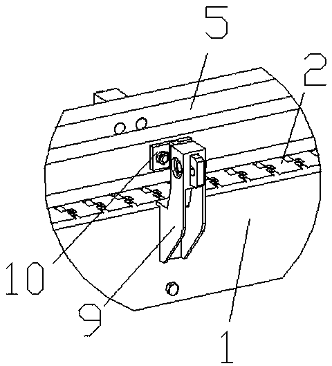
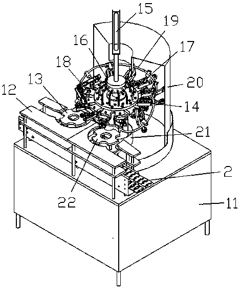
[0034] Such as Figure 1-Figure 8 As shown, the concrete structure of the present invention is: a kind of automatic filling machine of beverage bottle, and it comprises frame 1, and described frame 1 is provided with the conveyor chain 2 that cooperates with each other and conveying motor 3, and described machine The frame 1 is provided with a guardrail 5 that cooperates with the conveying chain 2. The conveying chain 2 is sequentially equipped with a flushing device 6, a liquid injection device 7 and a capping device 8 along the conveying direction. The liquid injection device 7 includes Liquid injec...


PUM


Abstract

The invention relates to an automatic filling machine for beverage bottles. The automatic filling machine for the beverage bottles comprises a rack, a conveying chain, a conveying motor, a guardrail,a flushing device, a liquid injection device and a gland device, wherein the liquid injection device comprises a liquid injection rack, a bottle inlet and outlet guide device is arranged on the liquidinjection rack, the bottle inlet and outlet guide device comprises a bottle guide groove, a bottle outlet turntable and a bottle inlet turntable, the liquid injection device further comprises a liquid injection turntable, a liquid injection bottle clamping rotating ring is arranged on the liquid injection turntable, a liquid injection gun is connected to the liquid injection turntable through a liquid injection telescopic supporting rod, the liquid injection gun comprises a vacuum suction pipe connected with the telescopic supporting rod, the upper part of the vacuum suction pipe is providedwith a suction pipe joint, a liquid injection pipe is arranged in the vacuum suction pipe, and the upper part of the liquid injection pipe penetrates through the vacuum suction pipe and is connected to a liquid injection box. According to the automatic filling machine for the beverage bottles, the liquid injection gun is designed to be a structure in which the liquid injection pipe is sleeved withthe vacuum suction pipe, when the liquid injection gun is inserted into bottle bodies, the liquid injection of the beverage bottles in the vacuum state can be realized, meanwhile, the beverage bottles are adsorbed on the liquid injection gun, the centrifugation in the rotating process is avoided, the structural cost of the turntables is saved, and the matching difficulty is reduced.

Description

[0001] Original application number: 2017107266438 [0002] Date of original filing: August 22, 2017 [0003] Applicant of the original case: Dongguan Ronggong Automation Technology Co., Ltd. [0004] Title of the original application: an automatic cleaning and filling machine for beverage bottles. technical field [0005] The invention relates to the field of beverage bottle filling equipment, in particular to an automatic filling machine for beverage bottles. Background technique [0006] With the improvement of people's living standards, the consumption of beverages is increasing. Most of the beverages in daily life are bottled, and most of the existing beverage bottle fillings are carried out by filling machines. [0007] Most of the existing beverage filling machines include beverage bottle conveying and liquid injection devices installed on the beverage bottle conveying line. Most of the existing liquid injecting devices directly inject liquid into the beverage bottle...

Claims


Application Information

Patent Timeline
Patent Type & Authority Applications(China)
IPC IPC(8): B67C3/24B67C3/26B67C7/00B67B3/20
CPCB67B3/20B67C3/24B67C3/26B67C7/0026B67C2007/006B67C2007/0066
Inventor 邓君杨坤
Owner DONGGUAN RONGGONG AUTOMATION TECH CO LTD
Why Eureka
Try Eureka