
Cable trench expansion joint structure and construction method thereof

A technology of cable trenches and expansion joints, which is applied in the direction of cable installation, ground cable installation, and building components, etc. It can solve the problem of uneven settlement of cable trench expansion joint structures, inability to transmit force and coordinated deformation of cable structures, and differential settlement of expansion joint interfaces To achieve the effect of improving reliability and safety, improving stiffness and force transmission characteristics, and improving construction quality

Pending Publication Date: 2020-02-21
SOUTH CHINA UNIV OF TECH
View PDF0 Cites 0 Cited by
  • Summary
  • Abstract
  • Description
  • Claims
  • Application Information

AI Technical Summary

Problems solved by technology

Due to the subsidence of the foundation soil in a 220KV high-voltage cable trench in Zhuhai, uneven settlement occurred at the expansion joint structure of the cable trench, which caused the expansion joint structure to open, causing safety hazards such as water seepage and cable shedding
[0004] The source of the safety hazards of the above-mentioned type of cable trench is that the expansion joint structure of the traditional cable trench is a concrete structure expansion joint set up in accordance with the construction specifications and requirements of the concrete structure, and the joint is only filled with asphalt, hemp and other materials to seal it. Due to the disconnection of the steel bar and concrete structure at the joint, the cable structures on both sides cannot transmit force and coordinate deformation. Under the disturbance of external factors, it is very easy to cause misalignment, differential settlement and cracking of the expansion joint interface. And other problems, and then there are problems such as damage to the internal high-voltage cables (stretching, falling off) and water seepage inside the cable trench, causing the cables to be soaked in water and other problems, endangering the safety of power grid operation

Method used


Image

  • Cable trench expansion joint structure and construction method thereof
  • Cable trench expansion joint structure and construction method thereof
  • Cable trench expansion joint structure and construction method thereof

Examples


Embodiment Construction

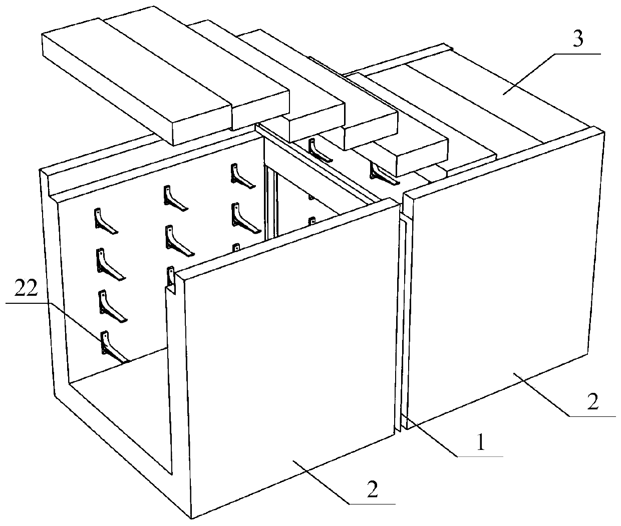
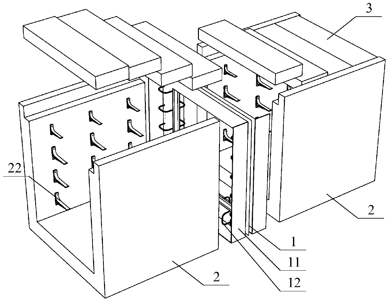
[0032] Such as Figure 1~2 As shown, it is a schematic diagram of the cable trench expansion joint structure of the present invention installed in the cable trench structure. The cable trench structure 2 is formed by pouring the steel cage after the steel bar 21 inside the cable trench structure is built, and then the cable trench structure 2 is installed. The cable brackets 22 on the side walls on both sides are used to place and limit the cables, and finally a prefabricated cable trench cover 3 is placed on the top of the cable trench structure 2 to form a closed space structure for protecting the cables.

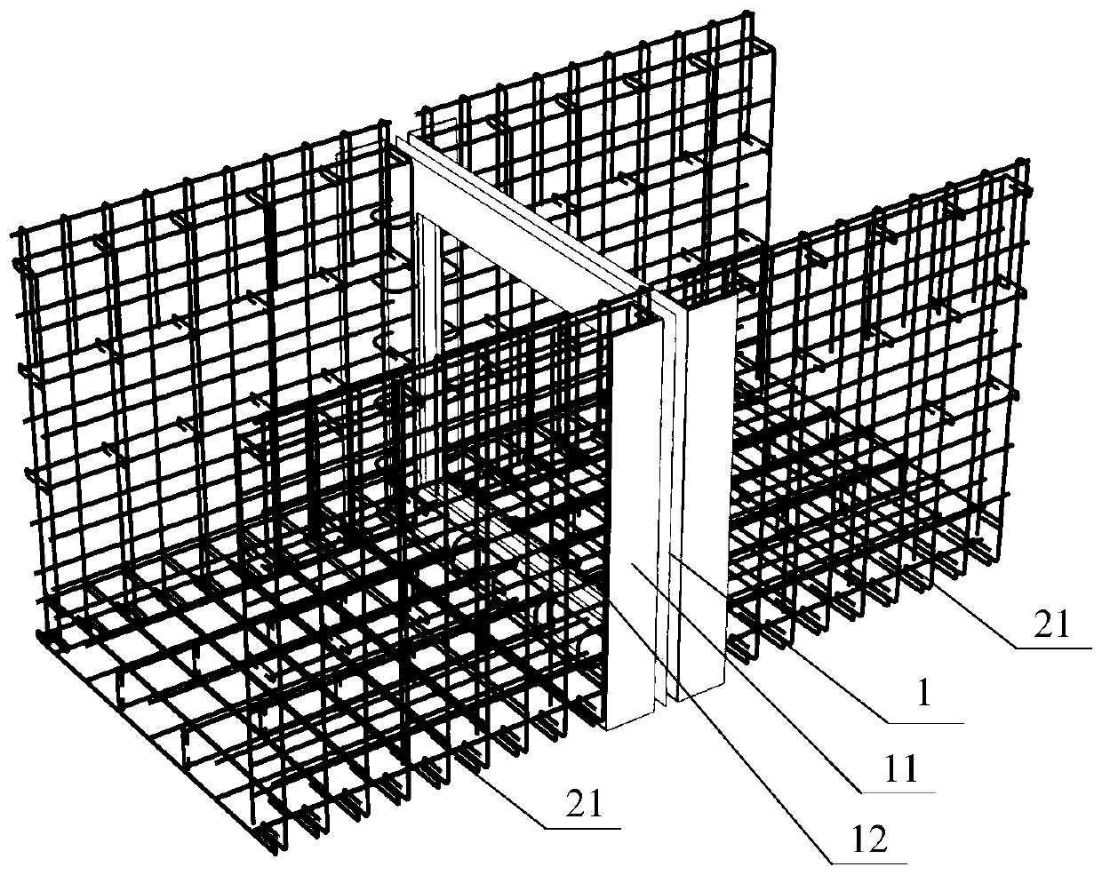
[0033] Such as Figure 3~4 As shown, there are several U-shaped overlapping steel bars 12 with appropriate spacing on both sides of the cable trench expansion joint structure, and the elastic section steel 1 of the expansion joint structure is connected to the internal steel bars 21 of the cable trench structure through the overlapping steel bars 12 during construction. ...


PUM

PropertyMeasurementUnit
Widthaaaaaaaaaa
Thicknessaaaaaaaaaa
Lengthaaaaaaaaaa

Abstract

The invention discloses a cable trench expansion joint structure and a construction method of the cable trench expansion joint structure. The cable trench expansion joint structure is of a prefabricated structure and comprises elastic steel shaped like a Chinese character "kou". The section of the elastic steel is shaped like the combination of a plurality of V shapes. A plurality of lap joint reinforcing steel bars are fixed to the two sides of the axis of the elastic steel. U-shaped water stopping belts are fixed to the two sides of the elastic steel axis along the outer edges of the elasticsteel. By means of the cable trench expansion joint structure and the construction method of the cable trench expansion joint structure, concrete structure thermal expansion and cold contraction expansion space requirements are met, the continuity of cable trench structures on the two sides of a cable trench expansion joint is ensured, the rigidity of the cable trench expansion joint structure is improved, and therefore the situation that the cable trench structures on the two sides are subjected to settlement or side movement, and therefore cables in the cable trench structures are stretched or drop is avoided. Moreover, the cable trench expansion joint structure and the construction method of the cable trench expansion joint structure adopt assembly type and standardized construction,so that the construction quality and progress of the cable trench expansion joint structure are ensured.

Description

technical field [0001] The invention relates to the field of electric power construction, in particular to a cable trench expansion joint structure and a construction method thereof. Background technique [0002] Due to the increasing demand for urban power supply, high-level voltage lines began to enter the central area of ​​the city, and gradually changed from aerial erection to underground laying, and cable trenches are one of the most commonly used structures for cable line laying. Compared with small-diameter cable tunnels and cable pipes, it has a series of advantages such as low cost and wider size, and is widely used in the laying of high-voltage cables in cities. [0003] However, with the process of urbanization, a large number of external operations such as engineering construction are always endangering the buried high-voltage cable lines, especially in the coastal soft soil areas of the Pearl River Delta, this problem is more prominent. Due to the subsidence of...

Claims


Application Information

Patent Timeline
IPC IPC(8): E04B1/68H02G9/02
CPCE04B1/68E04B1/6806E04B1/6812H02G9/02E04B2001/6818
Inventor 刘庭金廖强汤智钧蔡良怡
Owner SOUTH CHINA UNIV OF TECH
Features
  • Generate Ideas
  • Intellectual Property
  • Life Sciences
  • Materials
  • Tech Scout
  • Unparalleled Data Quality
  • Higher Quality Content
  • 60% Fewer Hallucinations
Learn More