An electro-hydraulic brake mechanism

A hydraulic brake and brake motor technology, applied in the direction of brake actuators, brake types, brake components, etc., can solve the problems of poor braking stability, inconvenient installation and fixing, and no limit function, etc. Dynamic stability, guaranteed braking ability, guaranteed braking effect

Active Publication Date: 2021-01-22
HEFEI ZHIHUI LONGTUTENG INTPROP CO LTD
View PDF6 Cites 0 Cited by
  • Summary
  • Abstract
  • Description
  • Claims
  • Application Information

AI Technical Summary

Problems solved by technology

[0006] In order to solve the above technical problems, the present invention provides an electro-hydraulic brake mechanism to solve the existing electro-hydraulic brake mechanism that does not have a limit function, is prone to jacking, cannot perform pressure relief, and has poor braking stability and insufficiency. Easy to install Fixed issues

Method used


Image

  • An electro-hydraulic brake mechanism
  • An electro-hydraulic brake mechanism
  • An electro-hydraulic brake mechanism

Examples


Embodiment Construction

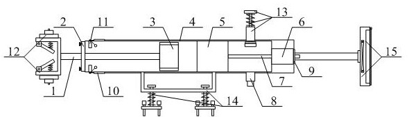
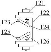
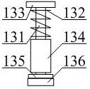
[0048] Below in conjunction with accompanying drawing, the present invention is described in detail, as shown in accompanying drawing 1 and accompanying drawing 2, a kind of electro-hydraulic braking mechanism comprises piston rod 1, fixed cover 2, piston disc 3, hydraulic cylinder 4, centrifugal pump 5, Brake motor 6, connecting shaft 7, oil pipe head 8, wiring bar 9, fixed line bar 10, limit switch 11, ventilated heat dissipation brake buffer deck structure 12, self-resetting pressure relief bar structure 13 , a shock-absorbing fixed mounting frame structure 14 and an intelligently controllable dust-proof operating machine structure 15, the lateral gap of the piston rod 1 runs through the inner middle position of the fixed cover 2; the piston disc 3 bolts are connected to the piston rod 1 The middle position of the left end; the fixed cover 2 bolts are connected to the left end of the hydraulic cylinder 4; the piston disc 3 is movably arranged inside the hydraulic cylinder 4 ...


PUM


Abstract

The invention provides an electrical hydraulic brake mechanism. The electrical hydraulic brake mechanism comprises a piston rod, a fixed cover, a piston disc, a hydraulic pump, a centrifugal pump, a brake motor, a connecting shaft, an oil pressure tube head, a line bank, a fixed line bank, a limiting switch, a blocking base structure capable of ventilating, radiating, braking and buffering, a self-return type pressure relief pressure rod structure, a damping type fixed mounting frame structure and an intelligently-controlled dustproof operator structure. According to the electrical hydraulic brake mechanism provided by the invention, a ventilating fan, a braking blocking base, a jointing base, a heat-conduction blocking plate, a movable shaft and a buffer spring are arranged, so that braking and radiating are facilitated, and brake effect is guaranteed; the ventilating fan can radiate a brake assembly to be braked inside the braking blocking base; the heat-conduction blocking plate canperform radiating work; and through buffer action of the buffer spring, the heat-conduction blocking plate can movably operate inside the jointing base through the movable shaft, so that brake stability is guaranteed.

Description

technical field [0001] The invention belongs to the technical field of mechanical equipment, and in particular relates to an electro-hydraulic braking mechanism. Background technique [0002] The brake mechanism is a device that has the functions of slowing down, stopping or keeping the moving parts or moving machinery in a stopped state. It is a mechanical part that stops or slows down the moving parts in the machine, commonly known as brakes and brakes; A certain force is applied to the part, and an external force opposite to the direction of operation is applied to the operating device, and the friction between the non-rotating element and the rotating element is used to prevent the rotation or rotation of the wheel, thereby forcing it to a certain extent brake. In order to reduce the braking torque and structural size, the brake is usually installed on the high-speed shaft of the equipment, but the large-scale equipment with high safety requirements (such as mine hoists...

Claims


Application Information

Patent Timeline
Patent Type & Authority Patents(China)
IPC IPC(8): F16D65/18F16D65/78F16D65/00F16F15/067F16D121/04F16D121/24
CPCF16D65/0018F16D65/18F16D65/78F16D2121/04F16D2121/24F16D2125/08F16F15/067
Inventor 王秋敏
Owner HEFEI ZHIHUI LONGTUTENG INTPROP CO LTD
Why Eureka
Try Eureka