

Hydraulic shock absorber
A technology of hydraulic shock absorber and hydraulic oil, applied in the field of hydraulic shock absorption, can solve the problems of inability to meet customer needs, unstable shock absorption performance, poor sealing performance, etc., to save space for shock absorbers, long service life, simple structure
- Summary
- Abstract
- Description
- Claims
- Application Information
AI Technical Summary
Problems solved by technology
Method used
Image

Examples
Embodiment Construction
[0021] The device of the present invention will be described in detail below in conjunction with the accompanying drawings and actual conditions.
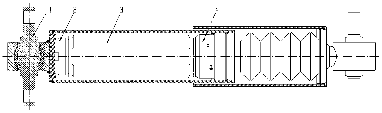
[0022] Such as figure 1 As shown, the hydraulic shock absorber includes the lower connection composition 1, the bottom valve composition 2, the inner oil cylinder composition 3, and the upper connection composition 4; the lower connection composition 1 and the upper connection composition 4 are connected by threads, and the bottom valve composition 2 and the inner cylinder are connected Composition 3 is packaged in lower connection composition 1, and a copper pad 32 is provided on the annular contact surface between bottom valve composition 2 and inner oil cylinder composition 3.
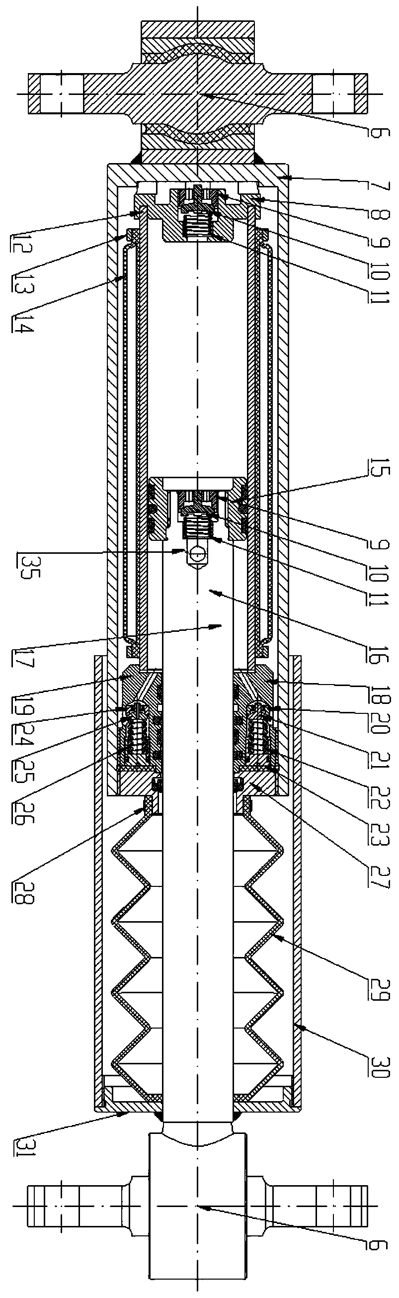
[0023] Such as figure 2 As shown, the lower connection component 1 is welded by the ball joint shaft assembly 6 and the outer oil cylinder 7, wherein the ball joint assembly 6 realizes the docking with the product to be damped. The bottom valve compos...
PUM
 Abstract
Description
Claims
Application Information