Optical axis angle adjustment and calibration method
A technology of optical axis and angle, applied in the direction of optical axis determination, testing optical performance, lens position determination, etc., can solve problems such as large stress and poor accuracy, and achieve the goal of improving stability, improving calibration efficiency, and improving calibration accuracy. Effect
- Summary
- Abstract
- Description
- Claims
- Application Information
AI Technical Summary
Problems solved by technology
Method used
Image
Examples
Embodiment 1
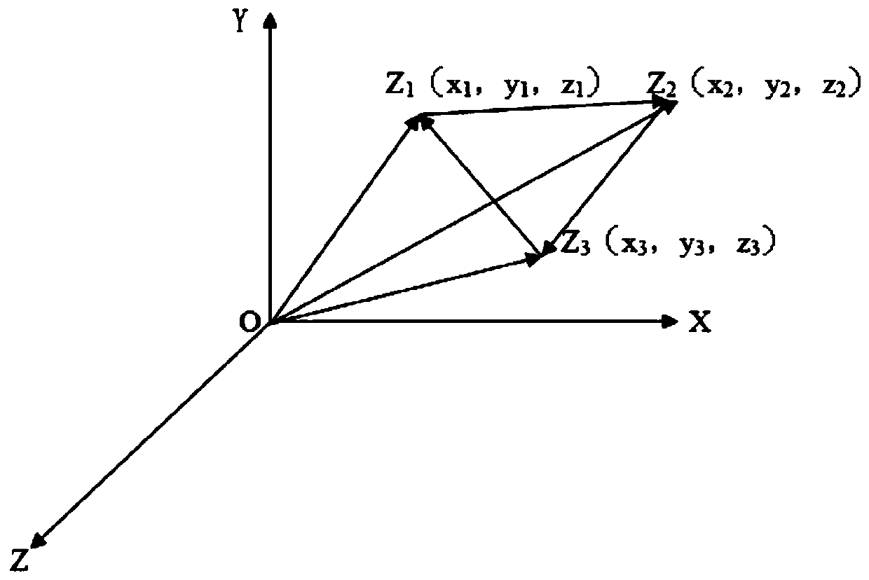
[0036] The azimuth deviation of the laser receiving optical axis is -1', the pitch deviation is -1.5', and the coordinates of the three spacers are as follows Figure 4 As shown, they are O(0, 0, 0), z1 (-42.5, 162.5, z1), z2 (219, 145, z2), z3 (219, 3.5, z3), and substitute into equations (1), ( 2), (3), can be solved
[0037] z1=0.029mm
[0038] z2 = 0.063mm
[0039] z3 = 0.032mm
Embodiment 2
[0041] The azimuth deviation of the laser receiving optical axis is -30", the pitch deviation is -1.5', and the coordinates of the 6 spacers are as follows Figure 5 As shown, they are O(0, 0, 0), z1 (0, 307.5, z1), z2 (230.4, 307.5, z2), z3 (0, 128.2, z3), z4 (230.4, 128.2, z4), Substituting z5(230.4, 0, z5) into equations (1), (2), (3), the solution is
[0042] z1=0.067mm
[0043] z2 = 0.084mm
[0044] z3 = 0.030mm
[0045] z4=0.045mm
[0046] z5 = 0.017 mm.
PUM
 Abstract
Description
Claims
Application Information
 - R&D
- Intellectual Property
- Life Sciences
- Materials
- Tech Scout
- Unparalleled Data Quality
- Higher Quality Content
- 60% Fewer Hallucinations
Browse by: Latest US Patents, China's latest patents, Technical Efficacy Thesaurus, Application Domain, Technology Topic, Popular Technical Reports.
© 2025 PatSnap. All rights reserved.Legal|Privacy policy|Modern Slavery Act Transparency Statement|Sitemap|About US| Contact US: help@patsnap.com


