Optical transceiver device
A technology for optical transceiver devices and optical emission components, applied in the field of optical fiber communication, can solve the problems of low efficiency and aberration of optical fiber adapters, and achieve the effects of enhancing strength, reducing aberration, and improving coupling efficiency
Pending Publication Date: 2020-02-21
APAT OPTOELECTRONICS COMPONENTS
0 Cites 2 Cited by
AI-Extracted Technical Summary
Problems solved by technology
The light emitted by the light emitting component needs to pass through various optical elements, and optical phenomena such as reflection and refraction will occur. Then when the light beam is converged into the fiber core of the fiber optic adapter through the lens, the focus ca...
Method used
In the present embodiment, optical fiber adapter 110 also receives the optical signal that wavelength is λ3 and λ4, and this optical signal is incident on the second optical filter 200, and the effect of second optical filter 200 is the beam transmission of λ3, And for the light beam reflection of λ4, the second optical filter 200 is a small-angle filter, and its design angle is 10°~20°, so even if the wavelength of λ3 and the wavelength of λ4 are relatively close, the second optical filter 200 can also To separate the two beams of light, the use of a small-angle filter can effectively meet the passband range and improve device performance.
It can be understood that the aspheric lens 180 converges the divergent light beam and is related to its curvature, thickness, and refractive index. By selecting a suitable aspheric lens 180, the light is converged, and the light emitted by the first light emitting assembly 120 is When passing through the aspheric lens 180 and the first filter 170, due to the different incident angles of the light, a certain phase difference will be generated, and the spherical aberration and aberration are compensated by the C-lens lens 140, and the light passes through the C-lens lens 140 , the light is converged twice, so that the light entering the isolator 130 is relatively concentrated, and the coupling efficiency is improved.
Optical transceiver device 1000 of the present invention comprises shell 100, optical fiber adapter 110, first light-emitting assembly 120, isolator 130 and C-lens lens 140, and optical fiber adapter 110 and first light-emitting assembly 120 are installed in shell respectively At opposite ends of 100, the isolator 130 is arranged in the casing 100, and is located between the first light emitting component 120 and the optical fiber adapter 110. Isolation, by setting the C-lens lens 140 in the tube shell 100, the C-lens lens 140 is set on the side of the isolator 130 away from the fiber adapter 110, and the C-lens lens 140 and the isolator 130 are arranged in the axial direction of the tube shell 100 Sequentially arranged at intervals, the C-lens lens 140 reconverges the light emitted by the first light emitting component 120 into the optical fiber of the optical fiber adapter 110, thus reducing aberrations and allowing more light to converge on the fiber end face of the optical fiber adapter 110 , enhance the intensity of the spot and improve the coupling efficiency.
[0043] Specifically, the tube shell 100 is a square socket, and is made of metal material with strong durability. In order to make the light emitted by the first light emitting component 120 enter the optical fiber of the fiber adapter 110 as much as possible, the light is converged by setting the C-lens lens 140, and in order to reduce the cost, the aperture of the isolator 130 needs to be reduced, so When the C-lens lens 140 is placed before the isolator 130, the light beam emitted by the first light emitting component 120 also needs to pass through other optical elements, because the incident angles of the converged light when incident on other optical elements are inconsistent, resulting in the final converged light Out of focus, causing aberrations. Finally, the spot of the emitted beam is relatively large and not concentrated, resulting in relatively low coupling efficiency. In order to solve the generated aberration, a C-lens lens 140 is provided before the isolator 130 to compensate for the aberration generated when the first light emitting component 120 passes through other optical elements, and finally converge the light to the optical fiber of the fiber optic adapter 110 Inside.
[0053] In addition, since the first light emitting assembly 120 is located at the end of the package 10, in order to reduce the volume of the entire optical transceiver device 1000, the first light emitting assembly 120 emits divergent light beams, the overall volume is small, and it is easy to install. An aspheric l...
Abstract
The invention discloses an optical transceiver device comprising a tube shell, a first light emitting assembly, an isolator, and a C-lens. An optical fiber adapter is installed at one end of the tubeshell. The first light emitting assembly is mounted at one end, far away from the optical fiber adapter, of the tube shell and is arranged opposite to the optical fiber adapter. The isolator is arranged in the tube shell between the first light emitting assembly and the optical fiber adapter and is used for isolating an optical signal received by the optical fiber adapter from an emitted optical signal. The C-lens arranged in the tube shell is arranged at one side, far away from the optical fiber adapter, of the isolator; the C-lens and the isolator are sequentially arranged at an interval inthe axial direction of the tube shell; and light emitted by the first light emitting assembly is converged into an optical fiber of the optical fiber adapter through the C-lens. The optical coupling efficiency of the optical transceiver device is high.
Application Domain
Coupling light guides
Technology Topic
Coupling efficiencyTransceiver +5
Image
Examples
- Experimental program(1)
Example Embodiment
[0033] The technical solutions in the embodiments of the present invention will be clearly and completely described below in conjunction with the accompanying drawings in the embodiments of the present invention. Obviously, the described embodiments are only a part of the embodiments of the present invention, rather than all the embodiments. Based on the embodiments of the present invention, all other embodiments obtained by those of ordinary skill in the art without creative work shall fall within the protection scope of the present invention.
[0034] It should be noted that all the directional indications (such as up, down, left, right, front, back...) in the embodiments of the present invention are only used to explain the difference between components in a specific posture (as shown in the accompanying drawings). If the relative positional relationship, movement situation, etc. change, the directional indication will change accordingly.
[0035] In the present invention, unless otherwise clearly specified and limited, the terms "connected", "fixed", etc. should be understood in a broad sense. For example, "fixed" can be a fixed connection, a detachable connection, or a whole; It is a mechanical connection or an electrical connection; it can be a direct connection or an indirect connection through an intermediate medium, and it can be the internal communication between two elements or the interaction relationship between two elements, unless specifically defined otherwise. For those of ordinary skill in the art, the specific meanings of the above terms in the present invention can be understood according to specific circumstances.
[0036] In addition, the descriptions related to "first", "second", etc. in the present invention are only for descriptive purposes, and cannot be understood as indicating or implying their relative importance or implicitly indicating the number of technical features indicated. Therefore, the features defined with "first" and "second" may explicitly or implicitly include at least one of the features. In addition, the technical solutions between the various embodiments can be combined with each other, but they must be based on what can be achieved by those of ordinary skill in the art. When the combination of technical solutions is contradictory or cannot be achieved, it should be considered that such a combination of technical solutions does not exist. , Is not within the protection scope of the present invention.
[0037] The present invention provides an optical transceiver device 1000.
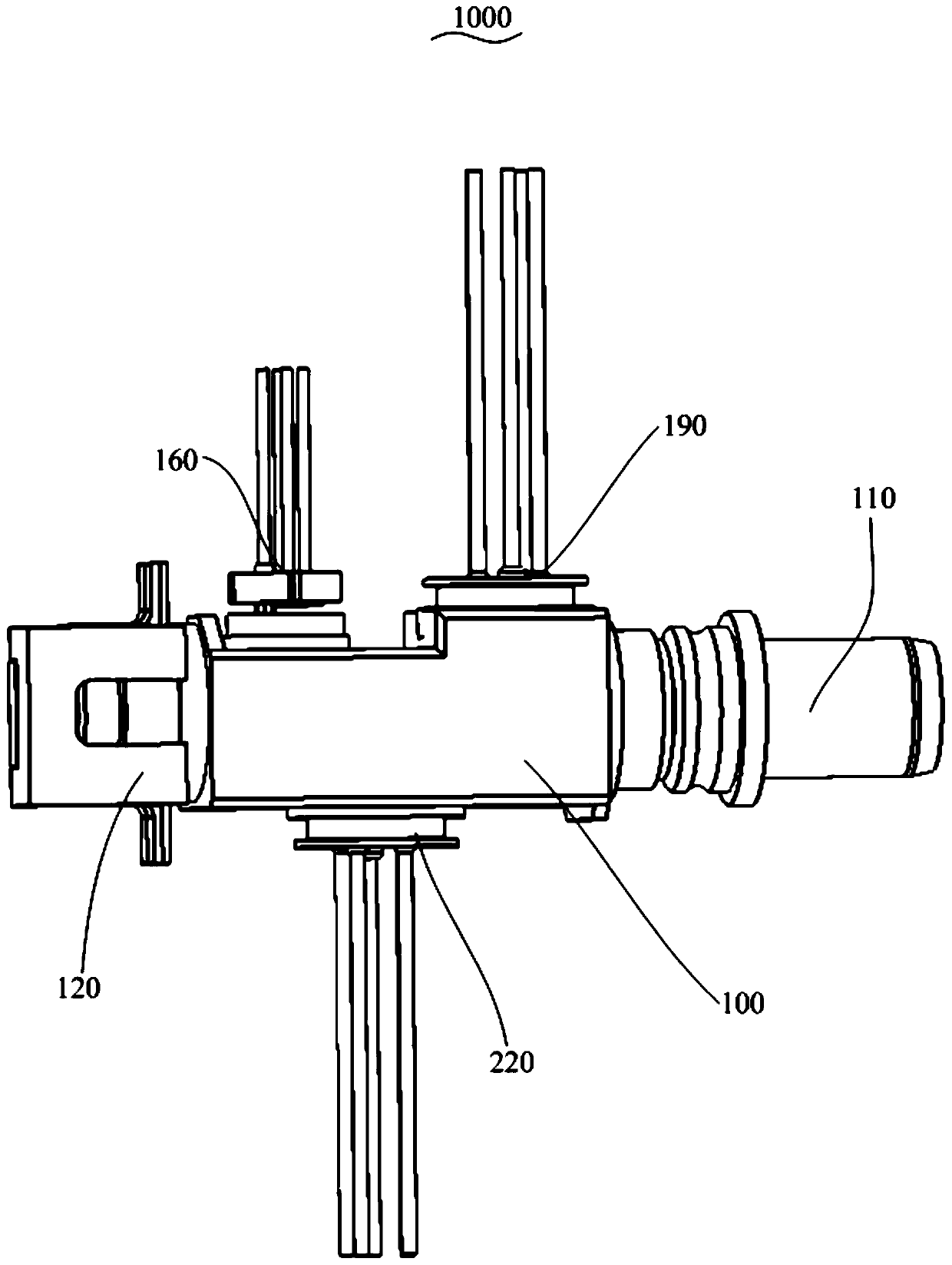
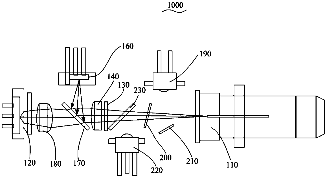
[0038] Reference Figure 1 to Figure 4 In the embodiment of the present invention, the optical transceiver device 1000 includes:
[0039] A tube housing 100, one end of which is installed with an optical fiber adapter 110;
[0040] A first light emitting component 120, the first light emitting component 120 is installed on the end of the tube housing 100 away from the optical fiber adapter 110 and arranged opposite to the optical fiber adapter 110;
[0041] The isolator 130 is arranged in the tube housing 100 and is located between the first light emitting assembly 120 and the optical fiber adapter 110, and the isolator 130 receives the optical fiber adapter 110 Isolate the optical signal from the emitted optical signal; and
[0042] C-lens lens 140, the C-lens lens 140 is arranged in the tube housing 100, and is arranged on the side of the isolator 130 away from the optical fiber adapter 110, the C-lens lens 140 and the The isolators 130 are arranged at intervals in the axial direction of the tube housing 100, and the light emitted by the first light emitting component 120 is condensed into the optical fiber of the optical fiber adapter 110 through the C-lens lens 140.
[0043] Specifically, the tube shell 100 is a square tube seat, and is made of metal material with strong durability. In order to make the light emitted by the first light emitting component 120 enter the optical fiber of the optical fiber adapter 110 as much as possible, the C-lens lens 140 is provided to converge the light. In order to reduce the cost, the aperture of the isolator 130 needs to be reduced. When the C-lens lens 140 is placed before the isolator 130, the light beam emitted by the first light emitting component 120 needs to pass through other optical elements. Because the incident angle of the condensed light is inconsistent when it is incident on other optical elements, the final condensed light Departure from focus, causing aberrations. Eventually, the spot of the emitted light beam is relatively large and not concentrated, resulting in relatively low coupling efficiency. In order to solve the aberration generated, a C-lens lens 140 is arranged before the isolator 130 to compensate the aberration generated when the first light emitting component 120 passes through other optical elements, and finally converge the light to the optical fiber of the optical fiber adapter 110 Inside.
[0044] It is understandable that, in order to ensure that the optical transceiver device 1000 can achieve the target coupling efficiency, the curvature, thickness, and refractive index of the C-lens lens 140 can be optimized through optical simulation software. For example, if the coupling efficiency is 60%, it means Since 60% of the light emitted by the first light emitting component 120 can enter the optical fiber of the optical fiber adapter 110, the thickness, curvature, and refractive index of the C-lens lens 140 required at this time can be obtained through optical simulation software. The processing method is a technical solution well known to those skilled in the art, and will not be specifically discussed here.
[0045] The optical fiber adapter 110 can transmit light beams with wavelengths λ1, λ2, λ3, and λ4. The first light emitting component 120 emits a light beam with a wavelength λ1. In this embodiment, λ1 is a laser with 1577 nm, which can be a parallel beam or a divergent beam. If it is a parallel beam, the parallel beam passes through the C-lens lens 140 and then converges into the optical fiber of the optical fiber adapter 110. If it is a divergent beam, a condensing lens can be arranged between the first light emitting component 120 and the C-lens lens 140 to form a convergent beam. The converged beam passes through the C-lens lens 140 again and is condensed into the optical fiber of the optical fiber adapter 110.
[0046] The optical transceiver device 1000 of the present invention includes a tube case 100, an optical fiber adapter 110, a first light emitting component 120, an isolator 130, and a C-lens lens 140. The optical fiber adapter 110 and the first light emitting component 120 are respectively mounted on opposite sides of the tube case 100. At both ends, the isolator 130 is arranged in the tube case 100 and is located between the first light emitting assembly 120 and the optical fiber adapter 110. The isolator 130 isolates the optical signal received by the optical fiber adapter 110 and the optical signal emitted by the optical fiber adapter 110. The C-lens lens 140 is arranged in the tube case 100, the C-lens lens 140 is arranged on the side of the isolator 130 away from the optical fiber adapter 110, and the C-lens lens 140 and the isolator 130 are sequentially spaced apart in the axial direction of the tube case 100 , The C-lens lens 140 re-converges the light emitted by the first light emitting component 120 into the optical fiber of the optical fiber adapter 110, so that aberrations can be reduced, so that more light can be condensed at the fiber end face of the optical fiber adapter 110, enhancing The intensity of the light spot improves the coupling efficiency.
[0047] Further, the optical transceiver device 1000 further includes a second light emitting component 160 arranged on the side wall of the tube case 100 and a first filter 170 arranged in the tube case 100. The first filter 170 is located close to the first light emitting component 120 and the second light emitting component 160, the first filter 170, the C-lens lens 140 and the isolator 130 are located on the tube housing 100 The axial direction is arranged at intervals;
[0048] The first filter 170 is used to transmit the light beam emitted by the first light emitting component 120 and reflect the light beam emitted by the second light emitting component 160, and the generated convergent light beams of two different wavelengths pass through the C The lens 140 converges into the optical fiber of the optical fiber adapter 110.
[0049] In this embodiment, the first filter 170, the C-lens lens 140 and the isolator 130 are coaxially arranged, the central axis of the second light emitting component 160 is perpendicular to the central axis of the first light emitting component 120, and the second light The emission component 160 emits a light beam with a wavelength of λ2. The light beam can be a parallel beam or a divergent beam. If it is a parallel beam, the parallel beam is reflected by the first filter 170 to form a convergent beam and a convergent beam formed by the first light emitting component 120 Together, they pass through the C-lens lens 140 and converge into the optical fiber of the optical fiber adapter 110. If it is a divergent light beam, a condensing lens can be arranged between the second light emitting component 160 and the first filter 170 to form a convergent beam. The converged light beam is reflected by the first filter 170 to form an intersection with the first light emitting component 120 The condensed light beams pass through the C-lens lens 140 and are condensed into the optical fiber of the optical fiber adapter 110. There is no restriction here.
[0050] The first filter 170 is located at the intersection of the light path emitted by the first light emitting component 120 and the light path emitted by the second light emitting component 160, and is used to transmit the light beam with the wavelength λ1 and reflect the light beam with the wavelength λ2. The C-lens lens 140 is used to converge the converged light beams with a wavelength of λ1 and a wavelength of λ2 to the optical fiber adapter 110, and the optical fiber of the optical fiber adapter 110 transmits optical signals of wavelengths λ1 and λ2 outward.
[0051] Please refer to Figure 2 to Figure 4 The optical transceiver device 1000 further includes an aspheric lens 180 arranged in the tube housing 100, the first light emitting component 120 emits a divergent light beam, and the aspheric lens 180 is located between the first filter 170 and the Between the first light emitting components 120, the divergent light beams emitted by the first light emitting components 120 form a convergent light beam.
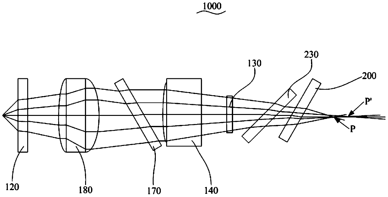
[0052] It can be understood that the aspheric lens 180 converges the diverging light beams and is related to its curvature, thickness, and refractive index. By selecting a suitable aspheric lens 180 to converge the light, the light emitted by the first light emitting component 120 passes through the aspheric surface. When the lens 180 and the first filter 170, because the incident angle of the light is different, a certain phase difference will occur. The spherical aberration and aberration are compensated by the C-lens lens 140, and the light is compensated by the C-lens lens 140. The secondary convergence makes the light entering the isolator 130 relatively concentrated and improves the coupling efficiency.
[0053] In addition, since the first light emitting component 120 is arranged at the end of the tube casing 10, in order to reduce the volume of the entire optical transceiver device 1000, the first light emitting component 120 emits a divergent light beam, which has a small overall volume and is easy to install. An aspheric lens 180 is provided between the first filter 170 and the first light emitting component 120, the aspheric lens 180 is coaxial with the fiber adapter 110, and the aspheric lens 180 is used to diverge the light emitted by the first light emitting component 120 Convergence is performed to form a convergent beam. After reaching the first filter 170, the converged beam is filtered by the C-lens lens 140 and is condensed into the optical fiber of the optical fiber adapter 110, which improves the coupling efficiency of the light transmission signal.
[0054] The complete light path diagram emitted by the first light emitting component 120 is as follows image 3 As shown, the convergence point P'of the near optical axis is rearward, and the convergence point P of the far optical axis is forward. The larger the distance between the convergence point P'of the near optical axis and the convergence point P of the far optical axis, the light spot Bigger. After C-lens lens 140 aberration compensation, the convergence point P'of the near optical axis and the convergence point P of the far optical axis are closer, that is, the convergence of the entire beam is more concentrated, so that more light can be coupled to the fiber adapter 110 in the fiber.
[0055] Further, the first filter 170 and the tube housing 100 are arranged at an angle of 45° in the axial direction.
[0056] In this embodiment, according to the transmission characteristics of the first filter 170, the divergence angle of the incident beam will affect the transmission characteristics of the first filter 170, and the transmission passband becomes smaller and the divergence loss increases, and this phenomenon It becomes more obvious as the incident angle increases. Generally, the polarization angle of the first filter 170 is 0 degrees or 45 degrees, so the best incident angle of the incident light beam is 0 degrees or 45 degrees. Since the central axes of the first light emitting component 120 and the second light emitting component 160 are vertically arranged, in order to reflect the light beam of the second light emitting component 160 to be parallel with the light beam of the first light emitting component 120, the first filter 170 It is arranged at 45° with the axial direction of the tube housing 100, and the reflective surface of the first filter 170 faces the second light emitting assembly 160.
[0057] Please refer again figure 2 In one embodiment, the second light emitting component 160 emits a divergent light beam, and the first filter 170 reflects the divergent light beam to form a convergent light beam. Since the second light emitting component 160 is arranged on the side of the tube case 10, in order to reduce the volume of the entire optical transceiver device 1000, the second light emitting component 160 emits a divergent light beam, and the overall volume is small and easy to install.
[0058] Please refer to figure 2 with Figure 4 , The optical transceiver device 1000 also includes:
[0059] The first light receiving component 190, the first light receiving component 190 is arranged on the side wall of the tube housing 100 and is spaced apart from the second light emitting component 160 along the axial direction of the tube housing 100;
[0060] A second filter 200, the second filter 200 is disposed adjacent to the first light receiving component 190; and
[0061] The reflecting sheet 210 is arranged opposite to the second light receiving assembly 220 and is arranged adjacent to the optical fiber adapter 110. The light beam emitted by the optical fiber adapter 110 is reflected by the second filter 200 to the The reflective sheet 210 emits the light beam to the first light receiving component 190.
[0062] In this embodiment, the optical fiber adapter 110 also receives optical signals with wavelengths λ3 and λ4. The optical signals are incident on the second filter 200. The second filter 200 is used to transmit the light beam of λ3, and to transmit the light beam of λ4. The second filter 200 is a small-angle filter with a design angle of 10°~20°, so that even if the wavelength of λ3 and the wavelength of λ4 are relatively close, the second filter 200 can combine the two beams The light is separated, and the small-angle filter can effectively meet the passband range and improve the performance of the device.
[0063] The light beam λ4 reflected by the second filter 200 is incident on the reflector 210. The reflector 210 totally reflects the light beam and is incident on the first light receiving component 190, and then the light beam is received by its internal detector to be converted into an electrical signal Thus, the receiving coupling of the first light receiving component 190 is realized.
[0064] In an embodiment, the second filter 200 and the vertical line of the central axis of the tube shell 100 are arranged at 13°. The reflector 210 and the axial direction of the tube shell 100 are arranged at 32°. The second filter 200 and the reflective sheet 210 can change the direction of the light path by 90 degrees, so that the light beam entering the first light receiving assembly 190 is parallel light.
[0065] Wherein, the second filter 200 cooperates with the reflective sheet 210, in addition to changing the light path of λ4 by 90 degrees, it can also better distinguish two similar received lights λ3 and λ4. Among them, λ3 is 1310nm and λ4 is 1270nm. The wavelengths of the two received lights are relatively close, and crosstalk will occur during reception. The second filter 200 transmits λ3 and reflects λ4 to separate the two beams, reducing light crosstalk. The problem.
[0066] Further, the optical transceiver device 1000 further includes a second light receiving assembly 220, which is arranged on the side wall of the tube housing 100 and is spaced apart from the first light receiving assembly 190; and
[0067] The third filter 230 is arranged adjacent to the isolator 130 and is located on the side of the isolator 130 away from the C-lens lens 140, the third filter 230 It is arranged opposite to the second light receiving component 220, and the light beam emitted by the optical fiber adapter 110 is reflected to the second light receiving component 220 through the third filter 230.
[0068] It is understandable that after the light beam λ3 transmitted from the second filter 200 is incident on the third filter 230, it is reflected by the third filter 230 to the second light receiving component 220, and then is detected by the inside of the light beam λ3. The light path completes the receiving coupling of the second light receiving component 220.
[0069] The first light-receiving component 190 and the second light-receiving component 220 are both installed on the side wall of the package 100 for receiving optical signals of different wavelengths. It can be understood that the first light-receiving component 190 and the second light-receiving component 220 can be Are arranged at intervals along the axial direction of the tube housing 100, or the first light receiving assembly 190 and the second light receiving assembly 220 are arranged on adjacent two sides of the tube housing 100, or the first light receiving assembly 190 and the second light receiving assembly 220 Are arranged on opposite sides of the tube case 100. In one embodiment, the first light receiving component 190 and the second light receiving component 220 are arranged on opposite sides of the tube case 100, and the second light receiving component 220 and the second light emitting component The components 160 are arranged at intervals along the axial direction of the tube shell 100, and the overall structure is more compact.
[0070] According to the installation positions of the first light receiving component 190 and the second light receiving component 220, the second filter 200 and the reflection sheet 210 respectively send light beams with a wavelength of λ4 to the first light receiving component 190, and the third filter 230 The light beams with the wavelength λ3 are respectively sent to the second light receiving component 220. In this embodiment, the first light receiving component 190 and the second light receiving component 220 are preferably arranged on opposite sides of the tube housing 100 and located between the first light emitting component 120 and the light adapter 110 to reduce the size of the tube housing. The overall length of 100 saves costs.
[0071] Furthermore, the third filter 230 and the tube housing 100 are arranged at an angle of 45° in an axial direction. Since the central axis of the second light receiving assembly 220 and the optical fiber adapter 110 are arranged perpendicularly, in order to reflect the light beam emitted by the optical fiber adapter 110 into a parallel light beam, the third filter 230 is arranged at an angle of 45° with respect to the axial direction of the package 100. The reflective surface of the three filter 230 faces the second light receiving assembly 220.
[0072] The optical transceiver device 1000 of the present invention includes two transmitting ends (a first optical transmitting component 120 and a second optical transmitting component 160) and two receiving ends (a first optical receiving component 190 and a second optical receiving component 220), an isolator 130 is located between the focal points of the first filter 170 and the third filter 230, and is used to block the light passing through the third filter 230 from entering the first filter 170. When the two sets of optical signals received by the optical fiber adapter 110 are respectively transmitted to the first light receiving component 190 and the second light receiving component 220, part of the optical signals will be reflected back into the first light emitting component 120 and the second light emitting component 160, thereby affecting them. For performance, the isolator 130 is used to isolate the optical signals received by the optical fiber adapter 110 to reduce the crosstalk between the optical transmitting signal and the optical receiving signal.
[0073] The isolator 130 is suitable for dual bands (1270nm, 1310nm). The first optical receiving component 190 receives 1310nm optical signals, and the second optical receiving component 220 receives 1270nm optical signals, which increases the return loss of the optical transceiver 1000 at the 1310nm wavelength end. Index, the optical path insertion loss is small, so that the anti-reflection ability of the optical transceiver 1000 is enhanced.
[0074] The above are only the preferred embodiments of the present invention, and do not limit the scope of the present invention. Under the inventive concept of the present invention, equivalent structural transformations made by using the contents of the description and drawings of the present invention, or direct/indirect use Other related technical fields are included in the scope of patent protection of the present invention.
PUM


Description & Claims & Application Information
We can also present the details of the Description, Claims and Application information to help users get a comprehensive understanding of the technical details of the patent, such as background art, summary of invention, brief description of drawings, description of embodiments, and other original content. On the other hand, users can also determine the specific scope of protection of the technology through the list of claims; as well as understand the changes in the life cycle of the technology with the presentation of the patent timeline. Login to view more.
Similar technology patents
Objective lens and optical head device provided with the same
InactiveUS20060007840A1reduce effective valuereduce aberration
Owner:NIDEC SANKYO CORP
Transmission type outer panoramic lens suitable for industrial detection
PendingCN112269251Areduce aberrationImproving Imaging Accuracy
Owner:南京华群光电技术有限公司
Projection tube
InactiveCN1203516CEnhanced prefocusreduce aberration
Owner:CAIHONG GRP ELECTRONICS CO LTD
Preparation method of micro-lens array, micro-lens array, system and equipment
PendingCN114325894Areduce aberrationgood structural stability
Owner:SHANGHAI INST OF MICROSYSTEM & INFORMATION TECH CHINESE ACAD OF SCI
High-efficiency hydrogen fluoride laser grating unstable resonator
ActiveCN106785855Areduce aberrationReduced diffraction loss
Owner:DALIAN INST OF CHEM PHYSICS CHINESE ACAD OF SCI
Classification and recommendation of technical efficacy words
- high strength
- reduce aberration
High-nitrogen austenitic stainless steel
Owner:DAIDO STEEL CO LTD
600-MPa grade vanadium-containing high-strength hot-rolled steel bar and production method thereof
Owner:HEBEI IRON AND STEEL
Electro-optical devices using dynamic reconfiguration of effective electrode structures
ActiveUS20110109824A1reduce aberrationimprove performance of lens
Owner:POINT FINANCIAL
Optical attachment for reducing the focal length of an objective lens
InactiveUS8903232B1reduce aberration
Owner:CALDWELL PHOTOGRAPHIC
Lens barrel, method for fixing lens, and working apparatus for fixing lens
ActiveUS20070121222A1reduce aberration
Owner:FUJI PHOTO OPTICAL CO LTD
Adjustment method and apparatus of optical system, and exposure apparatus
InactiveUS7083290B2reduce aberration
Owner:CANON KK
Methods of obtaining ophthalmic lenses providing the eye with reduced aberrations
InactiveUS20070121064A1reduce aberration
Owner:AMO GRONINGEN