Inspection robot instrument image recognition method and system based on computer vision

An inspection robot and computer vision technology, applied in the field of instrument image recognition, can solve the problems of instrument image recognition methods such as unstable parameters, difficult adjustment, unsafe human inspection, etc., so as to reduce the complexity and the required work The effect of increasing the amount, improving accuracy and speed, and avoiding a lot of tuning work

Inactive Publication Date: 2020-02-21
SHANDONG OUMA JIABAO ELECTRIC TECH CO LTD
View PDF0 Cites 10 Cited by
  • Summary
  • Abstract
  • Description
  • Claims
  • Application Information

AI Technical Summary

Problems solved by technology

[0005] In order to solve the deficiencies of the prior art, the present disclosure provides a computer vision-based inspection robot instrument image recognition method and

Method used


Image

  • Inspection robot instrument image recognition method and system based on computer vision
  • Inspection robot instrument image recognition method and system based on computer vision
  • Inspection robot instrument image recognition method and system based on computer vision

Examples


Embodiment 1

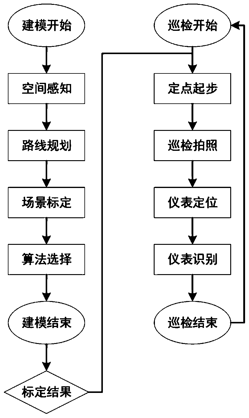
[0057] Such as figure 1 As shown, Embodiment 1 of the present disclosure provides a computer vision-based inspection robot meter image recognition method. The application module of this method mainly includes two parts, namely a scene modeling module and an actual use module.

[0058] The scene modeling module needs to use manpower to draw the cloud image of the specific scene and formulate the inspection points, and at the same time, it needs to record the calibration information required by the corresponding algorithm at each inspection point.

[0059] The inspection module is based on the scene modeling module. Based on the inspection location and calibration information set in the scene modeling stage, the captured pictures are processed by the algorithm module to obtain the final instrument reading.

[0060] The following is a detailed description of the overall application process of this method. The first is the scene modeling stage:

[0061] Step (1): Carry out 3D mod...

Embodiment 2

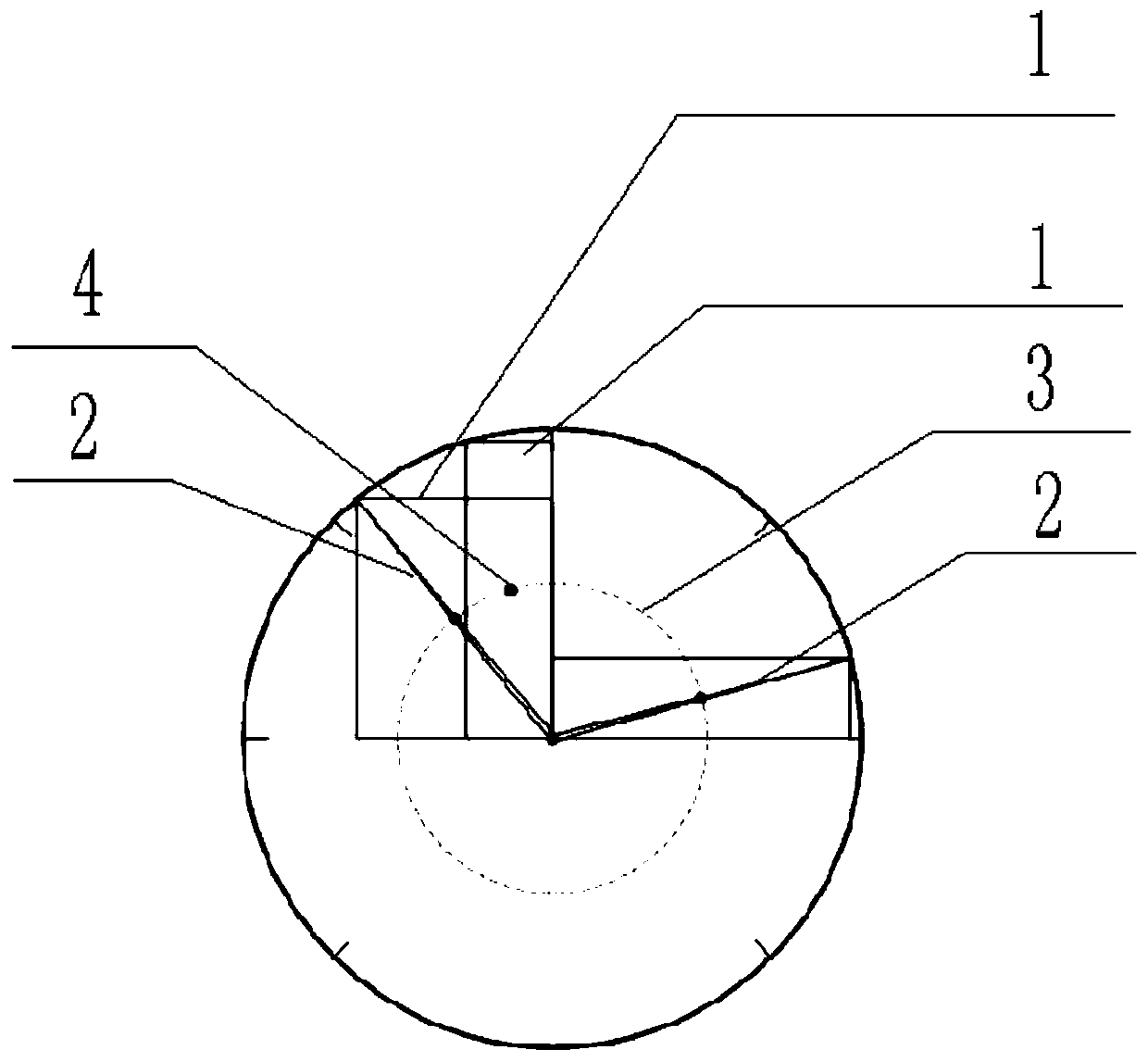
[0094] Embodiment 2 of the present disclosure provides a computer vision-based inspection robot instrument image recognition system, including a main control module and at least one inspection robot, the main control module has a built-in three-dimensional space model of the scene to be inspected, preset The inspection route of the inspection robot, the preset photo point, and the model, range, meter template picture and photo point number of the specified meter;

[0095] The inspection robot communicates with the main control module or the main control module is embedded in the inspection robot, and the inspection robot arrives at each inspection point along the inspection route in accordance with the specified sequence of numbers, and the meter is scanned according to the preset photographing point. Take pictures, encode the photos of the meters obtained, and then locate the meters according to the template matching algorithm, and then use the corresponding meter recognition ...


PUM


Abstract

The invention provides an inspection robot instrument image recognition method and system based on computer vision, and the method comprises the steps: constructing a three-dimensional space model ofa to-be-inspected scene, presetting an inspection route of an inspection robot, and presetting a photographing point position according to the position, orientation and illumination conditions of a target instrument; performing shooting calibration on the specified instrument based on the designed inspection route and the designed shooting point to obtain the model, the range, the instrument template picture and the shooting point number of the specified instrument; enabling the inspection robot to arrive at each inspection point along the inspection route according to a specified serial number sequence, shooting the instrument according to a preset shooting point position, encoding the obtained instrument picture, positioning the instrument according to a template matching algorithm, andperforming reading identification by utilizing an instrument identification algorithm corresponding to a pointer instrument or a digital instrument. According to the invention, the problems of insecurity of manual inspection and instability and difficult parameter adjustment of a traditional instrument image recognition method are solved, and the accuracy of instrument image recognition is greatlyimproved.

Description

technical field [0001] The present disclosure relates to the technical field of instrument image recognition, in particular to a computer vision-based inspection robot instrument image recognition method and system. Background technique [0002] The statements in this section merely provide background information related to the present disclosure and may not necessarily constitute prior art. [0003] With the advent of the intelligent era, using emerging computer vision technology to save more labor costs and improve the efficiency of practical applications is one of the future development trends. Image recognition technology has many application scenarios in life. How to carry computer vision-based image recognition methods on inspection robots to realize automated and intelligent inspections is one of the hotspots of current research. The purpose of instrument image recognition is to accurately find the position of the instrument in the picture and analyze the status of t...

Claims


Application Information

Patent Timeline
IPC IPC(8): G06K9/20G06K9/46G06K9/62G06N3/04G06N3/08
CPCG06N3/08G06V10/23G06V10/44G06N3/045G06F18/2411
Inventor 徐勇李传智郝朝阳李庆孙晓彬王树东武志强冯勇李志国宁利敏王明国
Owner SHANDONG OUMA JIABAO ELECTRIC TECH CO LTD
Why Eureka
Try Eureka