Pre-alignment device and silicon wafer pre-alignment method
A pre-alignment, silicon wafer technology, which is applied in photolithography process exposure devices, electrical components, semiconductor/solid-state device manufacturing, etc., can solve problems such as larger equipment size, unfavorable placement, and increase in the area occupied by the silicon wafer handover robot
- Summary
- Abstract
- Description
- Claims
- Application Information
AI Technical Summary
Problems solved by technology
Method used
Image
Examples
Embodiment 1
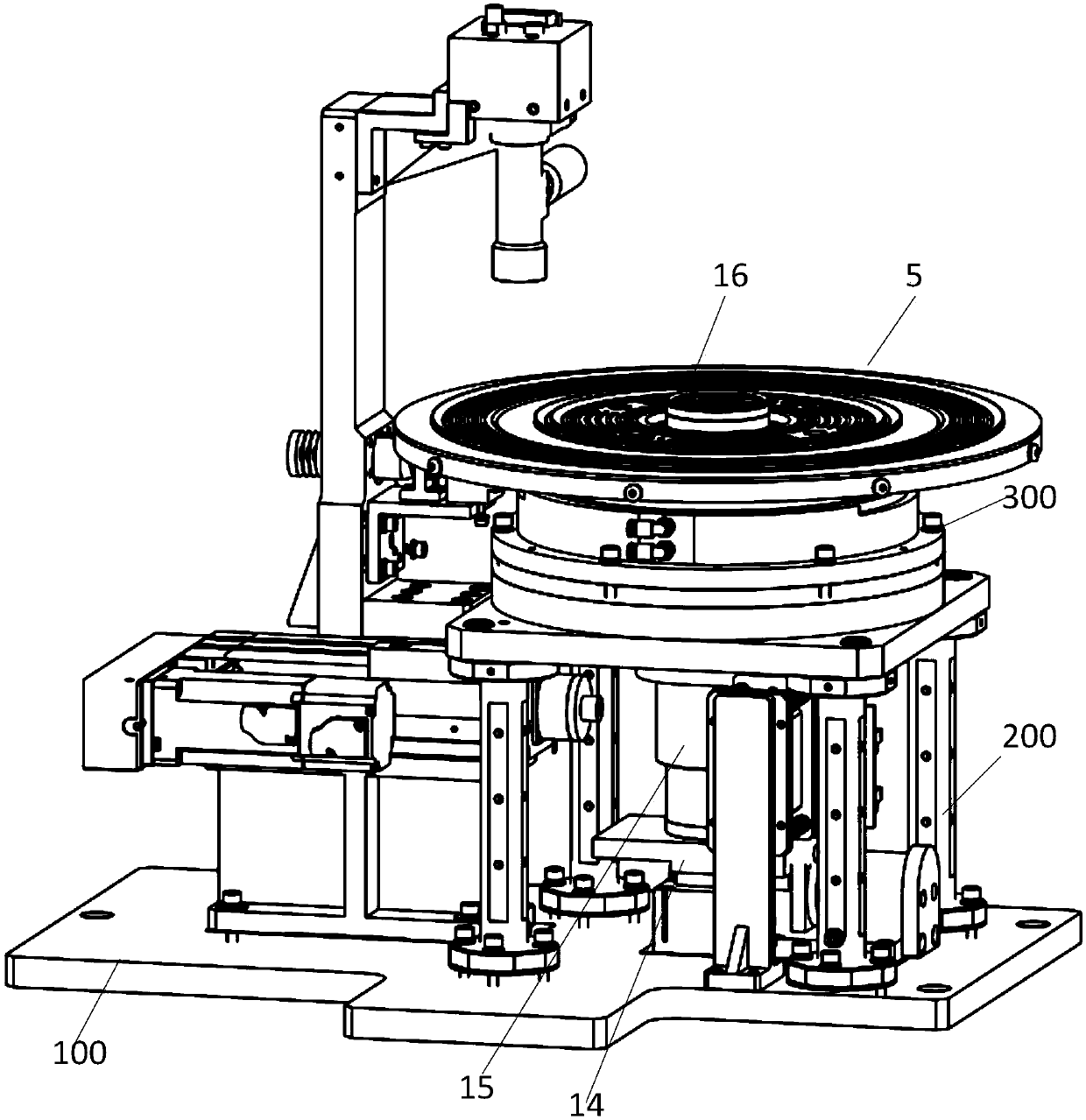
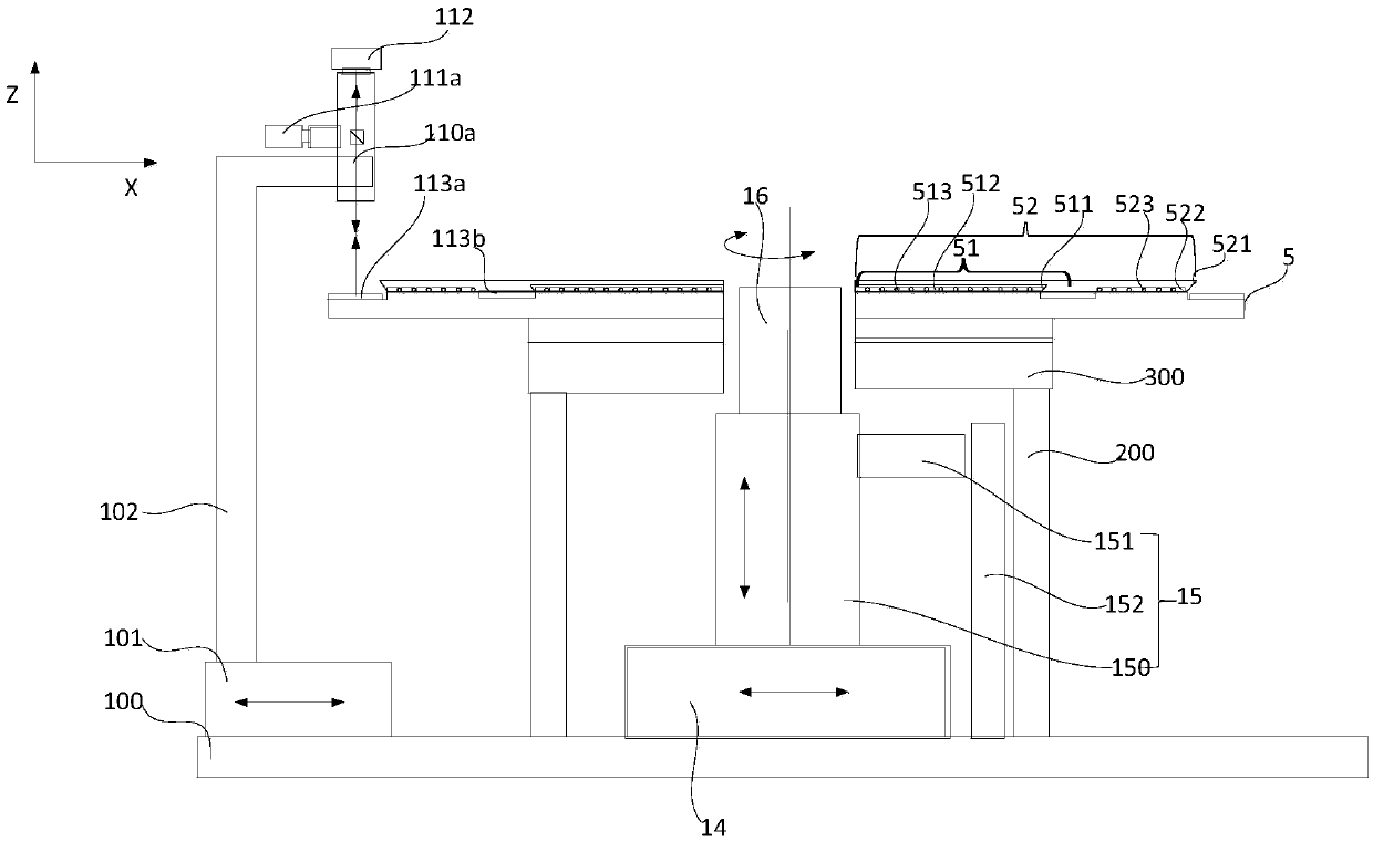
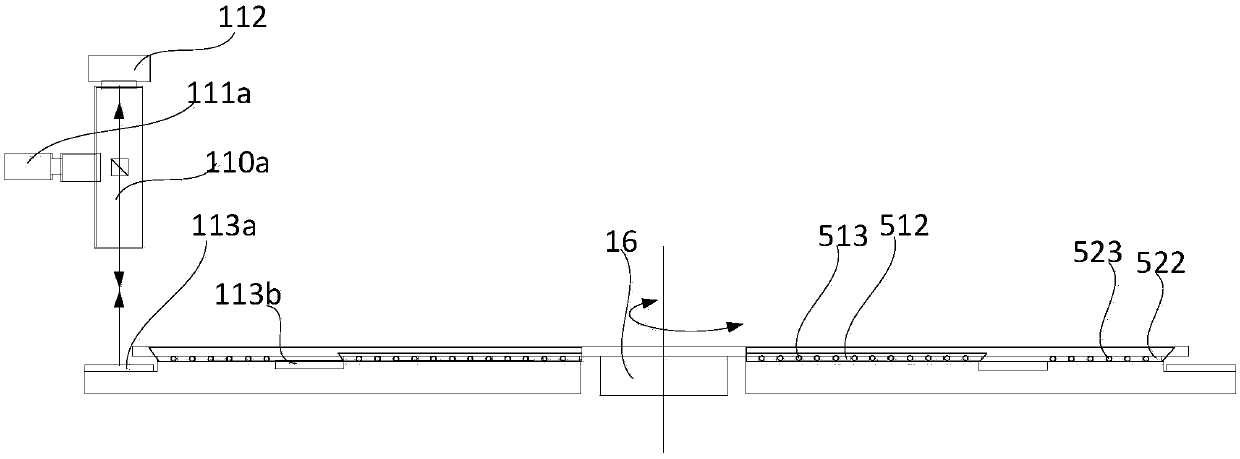
[0080] Please refer to figure 1 and figure 2 , an embodiment of the present invention provides a pre-alignment device, including: a base plate 100, a pre-alignment optical-mechanical unit, a rotary motion unit, a rotary bearing unit, a horizontal position compensation unit 14, a vertical motion unit 15, and a transfer bearing unit 16 .
[0081] The bottom plate 100 is used for installing and supporting the pre-alignment optical-mechanical unit, the rotary motion unit, the rotary bearing unit, the horizontal position compensation unit 14 , the vertical motion unit 15 and the transfer bearing unit 16 .
[0082] The rotating carrying unit includes a hollow carrying tray 5 for carrying silicon wafers and an adsorption assembly for absorbing the silicon wafers. The hollow carrying tray 5 includes a hollow area (not shown) in the center and a The carrying area of the periphery, the hollow area is used to provide the space for the handover carrying unit 16 to be set and moved, t...
Embodiment 2
[0119] Please refer to Figure 5 , in order to be compatible with the reflective pre-alignment method and the through-beam pre-alignment method, another embodiment of the present invention also provides a pre-alignment device, which is compatible with Figure 1 to Figure 4 Compared with the pre-alignment device in the shown embodiment, a set of opposite-type pre-alignment optical-mechanical components is added to the pre-alignment optical-mechanical unit, and the hollow carrying disc is at the outer edge of each carrying area Coating treatment, for example, can realize the function of reflecting the light of the first light source 111 a and transmitting the light of the second light source 111 b in these areas. Specifically, the pre-alignment optomechanical unit 11 in this embodiment includes a first lens 110 a , a second lens 110 b , a first light source 111 a , a second light source 111 b , a mirror 113 c and a camera 112 . Wherein, the installation positions of the first l...
Embodiment 3
[0123] In some cases, because the silicon wafer is too thin, the stiffness of the silicon wafer is weakened, even if the silicon wafer is placed in Figure 1 to Figure 5 On the shown pre-alignment device, there is still a certain slump phenomenon in the edge part of the silicon wafer not supported on the hollow carrier tray 5, so in another embodiment of the present invention, please refer to Figure 6 , in order to alleviate the problem that the edge of the silicon wafer rests, at least one ring of raised structures for supporting the silicon wafer is arranged on the outside of each suction cup. That is, the pre-alignment device of this embodiment, and Figure 1 to Figure 5 Compared with the pre-alignment device shown, a raised structure located on the outside of each suction cup is added to the hollow carrier plate 5, for example, a ring located on the outside of the first suction cup 511 is provided on the first bearing area 51. The protruding structure 514 is provided wit...
PUM
 Abstract
Description
Claims
Application Information
 - R&D
- Intellectual Property
- Life Sciences
- Materials
- Tech Scout
- Unparalleled Data Quality
- Higher Quality Content
- 60% Fewer Hallucinations
Browse by: Latest US Patents, China's latest patents, Technical Efficacy Thesaurus, Application Domain, Technology Topic, Popular Technical Reports.
© 2025 PatSnap. All rights reserved.Legal|Privacy policy|Modern Slavery Act Transparency Statement|Sitemap|About US| Contact US: help@patsnap.com


