Fluid driving centrifuge
A fluid-driven, centrifuge technology, applied in centrifuges and other directions, can solve the problems of difficulty in obtaining large torque and speed at the same time, complex structure, low efficiency, etc., and achieve the effect of small vibration, high separation efficiency and high speed
- Summary
- Abstract
- Description
- Claims
- Application Information
AI Technical Summary
Problems solved by technology
Method used
Image
Examples
Embodiment 1
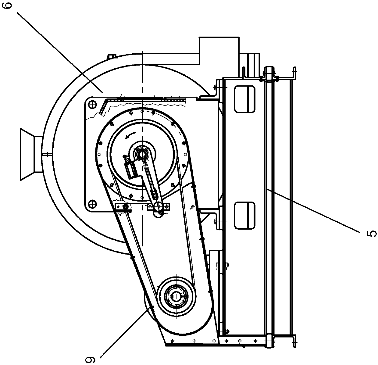
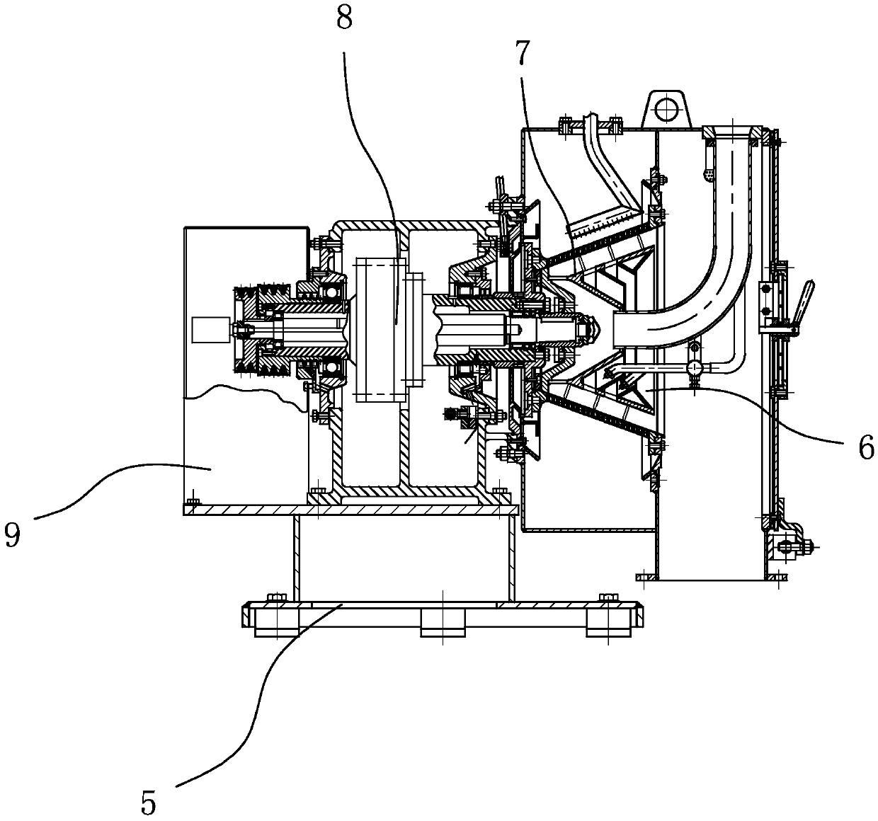
[0049] combine figure 1 and figure 2 As shown, this embodiment provides a fluid-driven centrifuge, which includes a frame 5, a separation device 6 and a fluid power device 9 are respectively provided on both sides of the frame, and the separation device 6 has a separation cover and A rotary impeller 7 arranged inside the separation cover, the fluid power device 9 is in driving connection with the rotary impeller 7 through a transmission mechanism 8, preferably, the transmission mechanism 8 includes a pulley assembly and a friction clutch assembly.
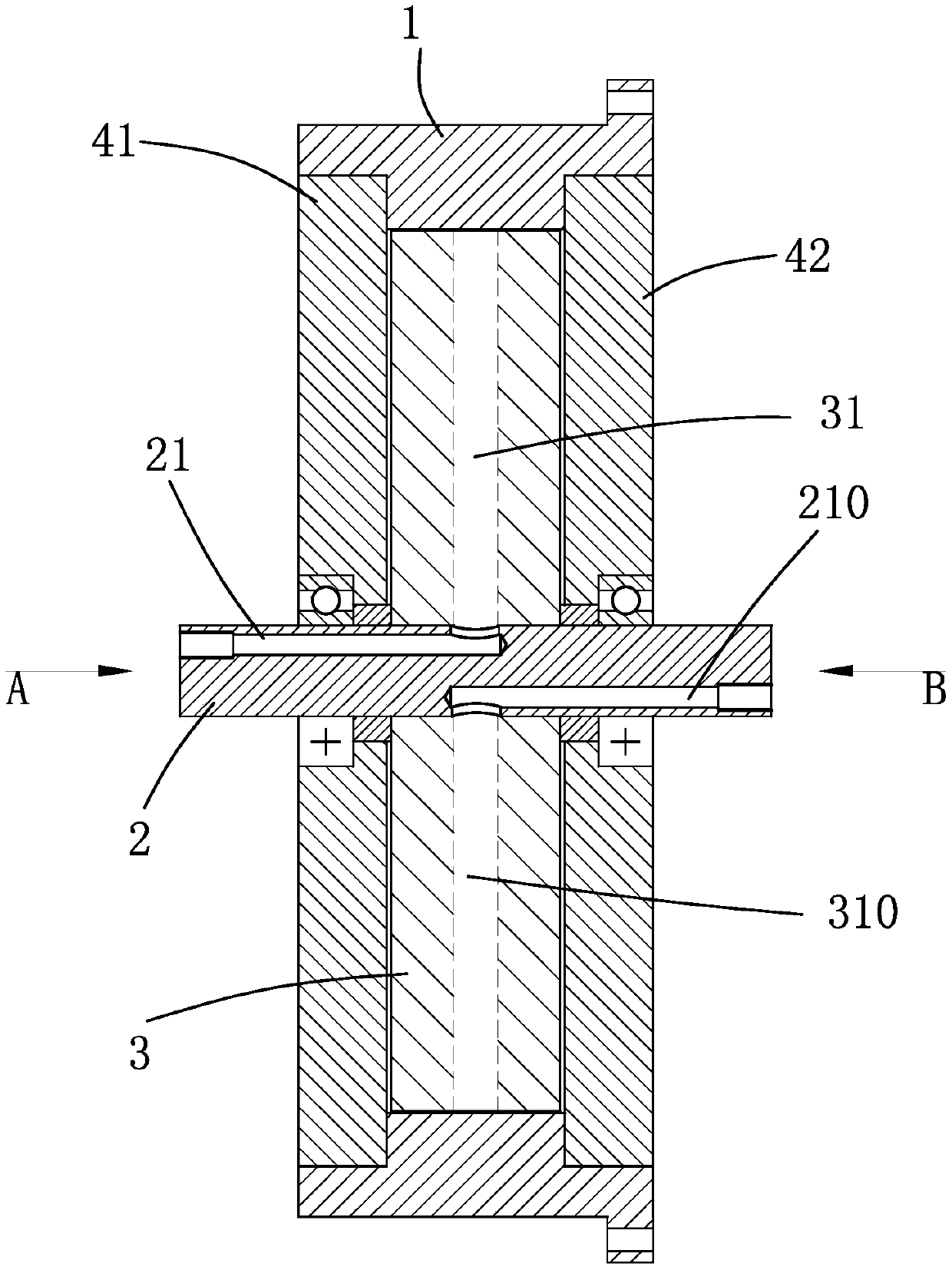
[0050] see Figure 3 to Figure 6 , the fluid power device of this embodiment, it comprises an outer ring 1, and its inner ring surface is circumferentially provided with a plurality of drive concave parts 11, and this outer ring 1 is connected with this transmission mechanism 8 by transmission; A core body 3, its coaxial It is arranged in the outer ring 1 and can rotate relative to the outer ring. The outer ring surface of the c...
Embodiment 2
[0070] The fluid-driven centrifuge of this embodiment is basically the same as Embodiment 1, and its main difference is:
[0071] see Figure 8 to Figure 11 , the fluid power device includes 2 independent work units to form a secondary drive structure, that is, the core body 3 is provided with 2 fluid passages along the circumferential direction, and each fluid passage includes an inlet flow passage 31 and a secondary flushing flow passage 300 of more than one stage and The drainage channel is arranged along the circumferential direction of the core body 3 . The fluid power device includes an outer ring 1, a plurality of driving recesses 11 are arranged on the inner ring surface of the outer ring; a core body 3 is coaxially arranged in the outer ring 1 and can rotate relative to the outer ring, and the outer ring surface of the core body is provided with 2 groups of spouts, discharge ports, and at least one flushing channel between each group of spouts and discharge ports; 2 ...
Embodiment 3
[0074] This embodiment is basically the same as Embodiment 1, and the main difference is that the fluid power device of the present invention includes 4 or more independent working units to form a multi-stage drive structure, and 3 or more fluid lines are arranged on the core along the circumferential direction. Channels, each fluid channel includes an inlet channel and a secondary flushing channel of more than one stage, and is arranged along the circumference of the core body and a drainage channel, and the inlet channel and the drainage channel are arranged on the mating surfaces of the left and right cores. The shaft is provided with the number of inlet shafts and outlet shafts corresponding to the number of fluid channels. The compressed fluid enters from the inlet shaft of the shaft, and is ejected through the core body inlet channel to act on the driving recess of the outer ring to drive the outer ring to rotate. Do work to realize the continuous output of power, and fin...
PUM
 Abstract
Description
Claims
Application Information
 - R&D
- Intellectual Property
- Life Sciences
- Materials
- Tech Scout
- Unparalleled Data Quality
- Higher Quality Content
- 60% Fewer Hallucinations
Browse by: Latest US Patents, China's latest patents, Technical Efficacy Thesaurus, Application Domain, Technology Topic, Popular Technical Reports.
© 2025 PatSnap. All rights reserved.Legal|Privacy policy|Modern Slavery Act Transparency Statement|Sitemap|About US| Contact US: help@patsnap.com


