Light flexible wing with variable-camber trailing edge

A flexible, trailing edge technology used in the aerospace field to improve overall aerodynamic performance, increase flight time and range, and improve overall performance

Pending Publication Date: 2020-02-25
CHINA ACAD OF AEROSPACE AERODYNAMICS
View PDF0 Cites 7 Cited by
  • Summary
  • Abstract
  • Description
  • Claims
  • Application Information

AI Technical Summary

Problems solved by technology

[0009] The technical problem of the present invention is: aiming at the limitations of traditional flaps and existing adaptive flaps, the present invention proposes a light-weight flexible variable trailing edge camber wing, which u

Method used


Image

  • Light flexible wing with variable-camber trailing edge
  • Light flexible wing with variable-camber trailing edge
  • Light flexible wing with variable-camber trailing edge

Examples


Embodiment Construction

[0032] The present invention is described in conjunction with accompanying drawing.

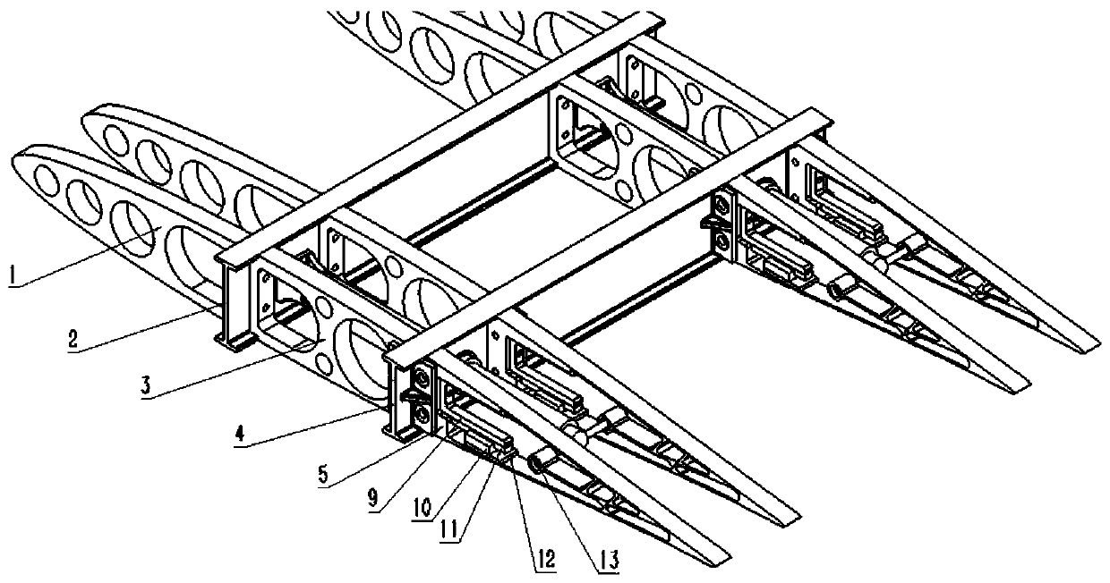
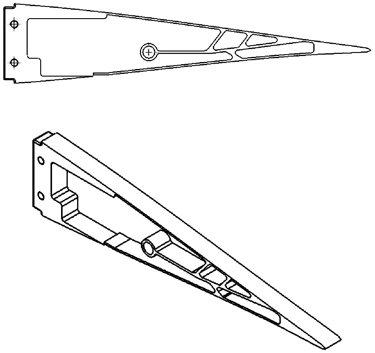
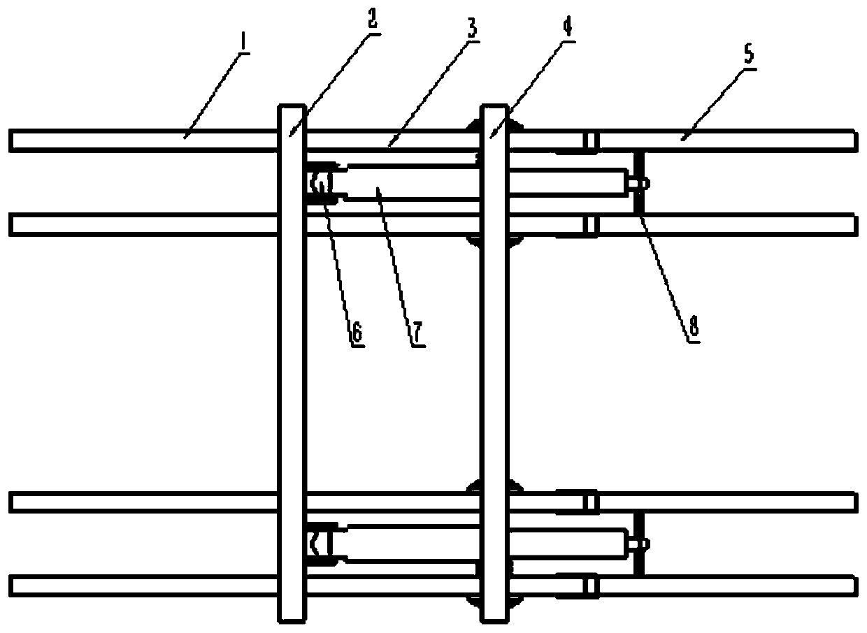
[0033] Such as Figure 1-5 As shown, the present invention provides a lightweight flexible variable trailing edge camber wing, comprising a leading edge rib 1, a front spar 2, a middle rib 3, a rear spar 4, a flexible trailing edge 5, and a motor support 6. Linear motor 7, motor and flexible trailing edge connecting rod 8, flexible trailing edge and guide rail connecting plate 9, slider 10, guide rail 11, slider and flexible trailing edge connecting plate 12, pull ring 13, skin;

[0034] The front rib 1 and the middle rib 3 are connected by the front spar 2 and fixed together; the middle rib 3 and the flexible trailing edge 5 are connected by the rear spar 4 and fixed together; the front end of the linear motor 7 is connected by the motor The support 6 is fixed on the front spar 2, and the rear end passes through the rear spar 4 and is connected to the pull ring 13 through the flexible rear ...


PUM


Abstract

The invention provides a light flexible wing with a variable-camber trailing edge. The light flexible wing comprises a leading edge ribbed plate (1), a front spar (2), a middle ribbed plate (3), a rear spar (4), the flexible trailing edge (5), a motor support base (6), a linear motor (7), a motor and flexible trailing edge connecting rod (8), a flexible trailing edge and guide rail connecting plate (9), a slider (10), a guide rail (11), a slider and flexible trailing end connecting plate (12), a pull ring (13) and a skin. The linear motor (7) is electrified, the pull ring (13) on the flexibletrailing edge (5) is pulled or pushed, under the action of the push-pull force, and the pull ring (13) does linear motion and drags the upper and lower sides of the flexible trailing edge (5) to be bent and deformed. Aiming at the limitations of a traditional wing flap and an existing adaptive wing flap, the whole structure can have high stability when a large deformation is generated, and the light flexible wing has the advantages that the mass is low, and the light flexible wing does not occupy extra wing space.

Description

technical field [0001] The invention relates to a lightweight flexible wing with variable trailing edge camber, which belongs to the field of aerospace. Background technique [0002] During the flight of the aircraft, because the flight speed is constantly changing, the wing with a fixed area cannot meet the different lift-to-drag ratio requirements of the aircraft during take-off and cruise flight, so the flaps came into being. The trailing edge flap can be deflected backward and downward around the axis, and it is mainly a lift-increasing device that increases the lift by increasing the camber of the wing. Its purpose is to provide a higher lift coefficient when the aircraft takes off and land, and reduce the takeoff and landing speed to shorten the roll distance. [0003] Flaps were first proposed by George Kelly and developed over the next century. At present, it is mainly divided into leading edge flaps and trailing edge flaps. [0004] The trailing edge flap is the ...

Claims


Application Information

Patent Timeline
IPC IPC(8): B64C3/48
CPCB64C3/48
Inventor 白鹏徐国武董二宝杨闰陈占军
Owner CHINA ACAD OF AEROSPACE AERODYNAMICS
Why Eureka
Try Eureka