A spraying and squeezing device for a raw foil machine

A foil machine and acid spraying technology, which is applied in the direction of electroforming and electrolysis, can solve the problems of affecting system stability, copper foil quality fluctuations, and increasing additional costs, achieving small, compact and reliable structure, and avoiding the use of scrapers , The effect of ensuring the quality of copper foil

Active Publication Date: 2020-09-22
西安航天新能源装备科技有限公司
View PDF8 Cites 0 Cited by
  • Summary
  • Abstract
  • Description
  • Claims
  • Application Information

AI Technical Summary

Problems solved by technology

[0005] At present, the main problems of the spraying liquid extrusion device in the foil forming machine are: 1. The scraper is easy to scratch the foil surface, which is not suitable for high-performance ultra-thin copper foil; 2. The cathode roller needs to be regularly polished during the foil production process. When hoisting the cathode roller, it is necessary to disassemble the spraying liquid extrusion device, and then adjust the device to continue production, which is time-consuming and laborious and increases additional costs; 3. The acid extrusion roller and liquid extrusion roller are unevenly squeezed, which affects the quality of the foil surface; 4. Water receiving box If it is not tight, there will be liquid leakage, and part of the foil washing water will not be recovered and flow into the system, resulting in changes in the parameters of the electrolytic solution, affecting the stability of the system, and causing fluctuations in the quality of copper foil

Method used


Image

  • A spraying and squeezing device for a raw foil machine
  • A spraying and squeezing device for a raw foil machine
  • A spraying and squeezing device for a raw foil machine

Examples


Embodiment Construction

[0037] The embodiments described below by referring to the figures are exemplary and are intended to explain the present invention and should not be construed as limiting the present invention.

[0038] In describing the present invention, it should be understood that the terms "center", "longitudinal", "transverse", "length", "width", "thickness", "upper", "lower", "front", " Orientation indicated by rear, left, right, vertical, horizontal, top, bottom, inside, outside, clockwise, counterclockwise, etc. The positional relationship is based on the orientation or positional relationship shown in the drawings, which is only for the convenience of describing the present invention and simplifying the description, rather than indicating or implying that the referred device or element must have a specific orientation, be constructed and operated in a specific orientation, Therefore, it should not be construed as limiting the invention.

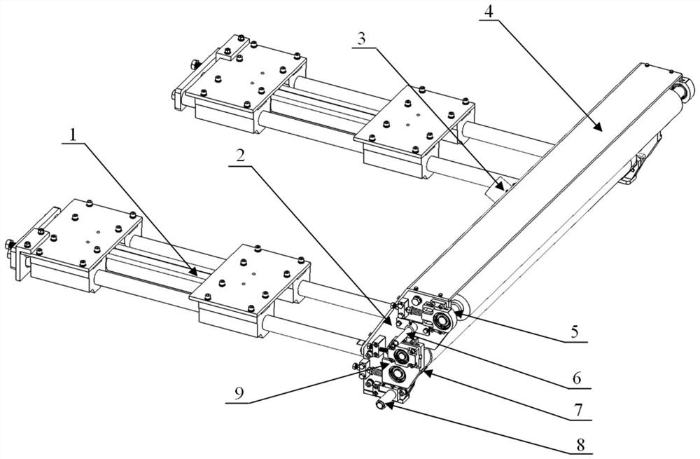
[0039] refer to figure 1 , a spraying and s...


PUM

PropertyMeasurementUnit
diameteraaaaaaaaaa

Abstract

The invention provides a spraying and liquid extruding device for a crude foil engine, and belongs to the technical field of electrolytic copper foil production. The spraying and extruding device comprises a device extending-retracting mechanism, a mounting rack, a water extruding roll component, a water spraying pipe fitting, a water receiving box, an acid spraying pipe fitting and a liquid extruding roll component, wherein the mounting rack is of a frame structure, and mounting end plates are symmetrically arranged at two ends of the frame structure; the mounting rack is used for mounting ,supporting and connecting other components; one side of the mounting rack is connected with the device extending-retracting mechanism, and the water extruding roll component, the water spraying pipe fitting, the water receiving box, the acid spraying pipe fitting and the liquid extruding roll component are mounted on the other side of the mounting rack and between the two mounting end plates; thedevice extending-retracting mechanism adopts a cylinder linear bearing mechanism; the cylinder controls the extending-retracting stroke of the device extending-retracting mechanism, and further controls the position of the mounting rack; and the distance between a roller and a cathode roller is finely adjusted by mounting adjusting mechanisms in the liquid extruding roll component and the water extruding roll component. The spraying and liquid extruding device is compact and reasonable in structure, has no liquid leakage phenomenon, can perform copper coil production only through fine adjustment after the cathode roller is hung, and can accurately and quickly adjust.

Description

technical field [0001] The invention belongs to the technical field of electrolytic copper foil production equipment, and in particular relates to a spraying liquid extrusion device for a foil raw machine. Background technique [0002] Electrolytic copper foil is an indispensable main raw material for making printed circuit boards (PCB), copper clad laminates (CCL) and lithium batteries (Li-ion). Electrolytic copper foil is mainly produced by a raw foil unit. The raw foil unit mainly includes two key equipments: a foil machine and a cathode roller. The cathode roller is installed in the anode tank of the foil machine. The anode tank is connected to the positive pole of the power supply, and the cathode roller is connected to the negative pole of the power supply. , under the action of a series of other supporting systems, the surface of the rotating cathode roller is deposited to form copper foil, and then a series of processes such as stripping, passivation, water washing, ...

Claims


Application Information

Patent Timeline
Patent Type & Authority Patents(China)
IPC IPC(8): C25D1/04
CPCC25D1/04
Inventor 陈浩杜英军徐浩天韩学灵武红霞朱晓冬徐卫兵傅毅恺张雨霏强亚宏周转红
Owner 西安航天新能源装备科技有限公司
Why Eureka
Try Eureka