
Non-contact electric field measurement system and method for fault indicator

A fault indicator, non-contact technology, used in electrostatic field measurement, short-circuit test and other directions, can solve the problem of inability to judge the fault of the distribution network, and achieve the effect of meeting the needs of live loading and unloading, simple design, and improved insulation performance

Pending Publication Date: 2020-02-25
中电装备山东电子有限公司
View PDF0 Cites 0 Cited by
  • Summary
  • Abstract
  • Description
  • Claims
  • Application Information

AI Technical Summary

Problems solved by technology

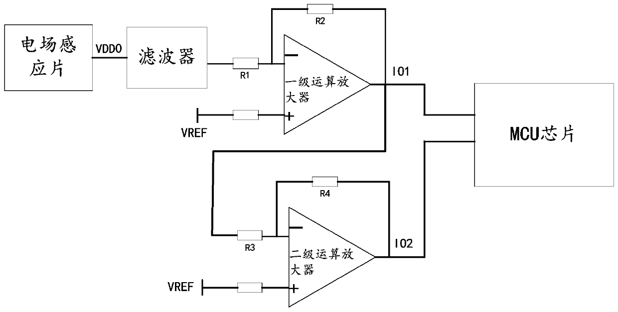
[0005] The purpose of the present invention is to provide a non-contact electric field measurement system and method for a fault indicator, which aims to solve the problem that the fault in the distribution network cannot be accurately judged in the prior art, realize the conditions of adapting to different conductors of overhead lines, and effectively judge Line faults to ensure the smooth operation of the distribution network

Method used


Image

  • Non-contact electric field measurement system and method for fault indicator

Examples


Embodiment Construction

[0020] In order to clearly illustrate the technical features of the present solution, the present invention will be described in detail below through specific implementation methods and in conjunction with the accompanying drawings. The following disclosure provides many different embodiments or examples for implementing different structures of the present invention. To simplify the disclosure of the present invention, components and arrangements of specific examples are described below. Furthermore, the present invention may repeat reference numerals and / or letters in different instances. This repetition is for the purpose of simplicity and clarity and does not in itself indicate a relationship between the various embodiments and / or arrangements discussed. It should be noted that components illustrated in the figures are not necessarily drawn to scale. Descriptions of well-known components and processing techniques and processes are omitted herein to avoid unnecessarily lim...


PUM


Abstract

The invention provides a non-contact electric field measurement system and method for a fault indicator. According to the embodiment of the invention, an electric field induction sheet, a signal conditioning unit and a MCU chip are arranged on a live line, an induced voltage signal is input into the signal conditioning unit through the electric field induction sheet, the signal conditioning unit outputs an output signal used for MCU chip processing, therefore, the fault indicator can adapt to conditions of different wires of an overhead line, line faults are effectively judged, meanwhile, a circuit adopts a non-contact mode, the live-line loading and unloading requirements can be met, and the stable operation of a power distribution network is guaranteed.

Description

technical field [0001] The invention relates to the technical field of power supply and distribution fault detection, in particular to a non-contact electric field measurement system and method for a fault indicator. Background technique [0002] In the small current system of overhead lines, under normal operation, under the same voltage, the phase electric field strength of the three phases is the same, and the three phases maintain symmetry. When a single-phase ground fault occurs, the phase electric field strength changes with the change of the phase voltage, and the grounding characteristics can be reflected by the change of the phase electric field strength. [0003] At present, the fault indicator of transient recording type is widely used in the small current system of overhead lines. The acquisition unit of the fault indicator monitors the current of the corresponding phase line and the electric field to the ground, indicates the short-circuit fault on the spot, and...

Claims


Application Information

Patent Timeline
Patent Type & Authority Applications(China)
IPC IPC(8): G01R29/12G01R31/52
CPCG01R29/12
Inventor 吴国强刘培于泳朱德良王利宁王先强刘孟臣高家皓董其泉张珊珊黄菁菁刘升师晓萌
Owner 中电装备山东电子有限公司
Learn More