

Edge polishing device for office furniture production
An edge grinding and furniture technology, applied in grinding devices, grinding drive devices, grinding/polishing safety devices, etc., can solve the problems of environmental worker hazards, no dust absorption, large dust, etc., to reduce harm and improve practicality. Sexual, easy-to-clean effect
- Summary
- Abstract
- Description
- Claims
- Application Information
AI Technical Summary
Problems solved by technology
Method used
Image

Examples
Embodiment 1
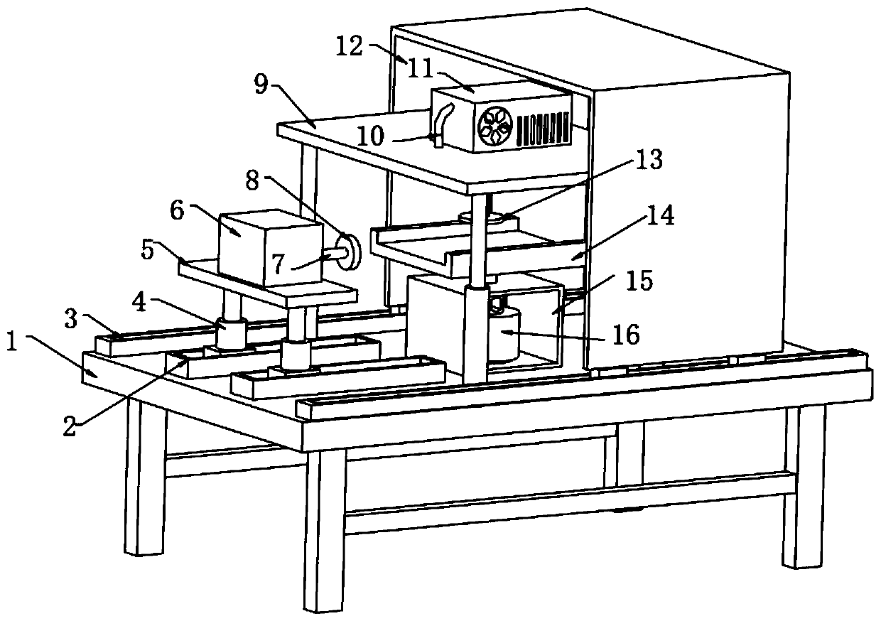
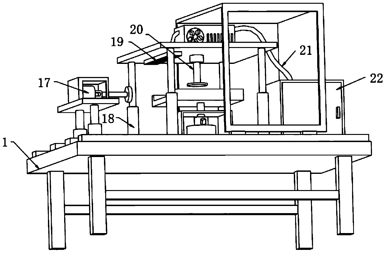
[0028] refer to figure 1 and figure 2 , an edging device for office furniture production, including a workbench 1, the top outer wall of the workbench 1 is welded with second hydraulic rods 18 distributed equidistantly, and the top outer wall of the second hydraulic rod 18 is fixed with the same transverse Plate 9, the bottom outer wall of the horizontal plate 9 is fixed with a dust suction disc 19 by screws, and the top outer wall of the horizontal plate 9 is welded with a fan 11, and the input end of the fan 11 is connected to the inner wall of one side of the dust suction disc 19 through a flange. A dust suction pipe 10, the top outer wall of the workbench 1 is fixed with a dust collection box 22 by screws, and the top inner wall of the dust collection box 22 and the output end of the fan 11 are connected with the same dust guide pipe 21 through a flange, and the workbench 1 The top outer wall of the workbench 1 is fixed with a protective mechanism and a grinding mechanis...
Embodiment 2
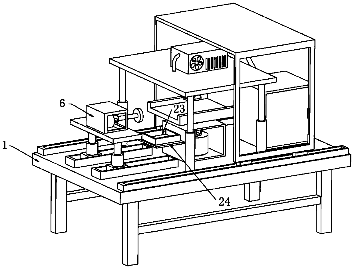
[0037] refer to image 3 , a kind of edging device for office furniture production, also includes the connecting plate 24 welded on the outer wall of one side of the motor box 15, the top outer wall of the connecting plate 24 is fixed with the waste material groove 23 by screws, in addition, when the sand disc 8 is grinding the plate , larger debris will directly fall into the waste chute 23, which is convenient for cleaning the surface of the workbench
[0038] Working principle: connect the equipment to the power supply, place the plate on the placement plate 14, connect the first hydraulic rod 4 and the second hydraulic rod 18 to the hydraulic system, adjust the length of the second hydraulic rod 18 to fix the plate with the fixing plate 13 , adjust the length of the first hydraulic rod 4, so that the height of the sand table 8 is the same as the height of the plate, adjust the electric slide rail 2, adjust the position of the protective cover 12, turn on the first motor 17...
PUM
 Abstract
Description
Claims
Application Information