Assembling device for core sponge of evaporator assembly

An evaporator assembly and assembly device technology, applied in the direction of measuring devices, workpiece clamping devices, instruments, etc., can solve the problems of wrong position of expansion valve, high equipment cost, wrong pasting position, etc., and realize the function of changing models and automation The effect of high degree and high assembly efficiency

Pending Publication Date: 2020-02-28
DONGFENG BEHR THERMAL SYST
View PDF0 Cites 2 Cited by
  • Summary
  • Abstract
  • Description
  • Claims
  • Application Information

AI Technical Summary

Problems solved by technology

There are the following risks: 0.5 of the core sponge is missing, the pasting position is wrong; the expansion valve 0.4 is in the wrong position; the evaporator core is 0.1 and the model is

Method used


Image

  • Assembling device for core sponge of evaporator assembly
  • Assembling device for core sponge of evaporator assembly
  • Assembling device for core sponge of evaporator assembly

Examples


Embodiment Construction

[0035] The present invention will be further described below in conjunction with the accompanying drawings and specific embodiments.

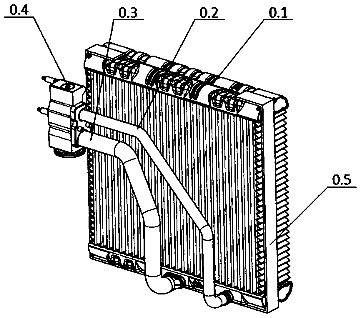
[0036] Such as figure 1 As shown, the evaporator assembly is composed of evaporator core 0.1, high-pressure pipe 0.2, low-pressure pipe 0.3, expansion valve 0.4 and core sponge 0.5, wherein: high-pressure pipe 0.2 and low-pressure pipe 0.3 are welded to the evaporator core by brazing On 0.1, the expansion valve 0.4 is installed on the high-pressure pipe 0.2 and the low-pressure pipe 0.3, and the core sponge 0.5 is pasted on the evaporator core 0.1.

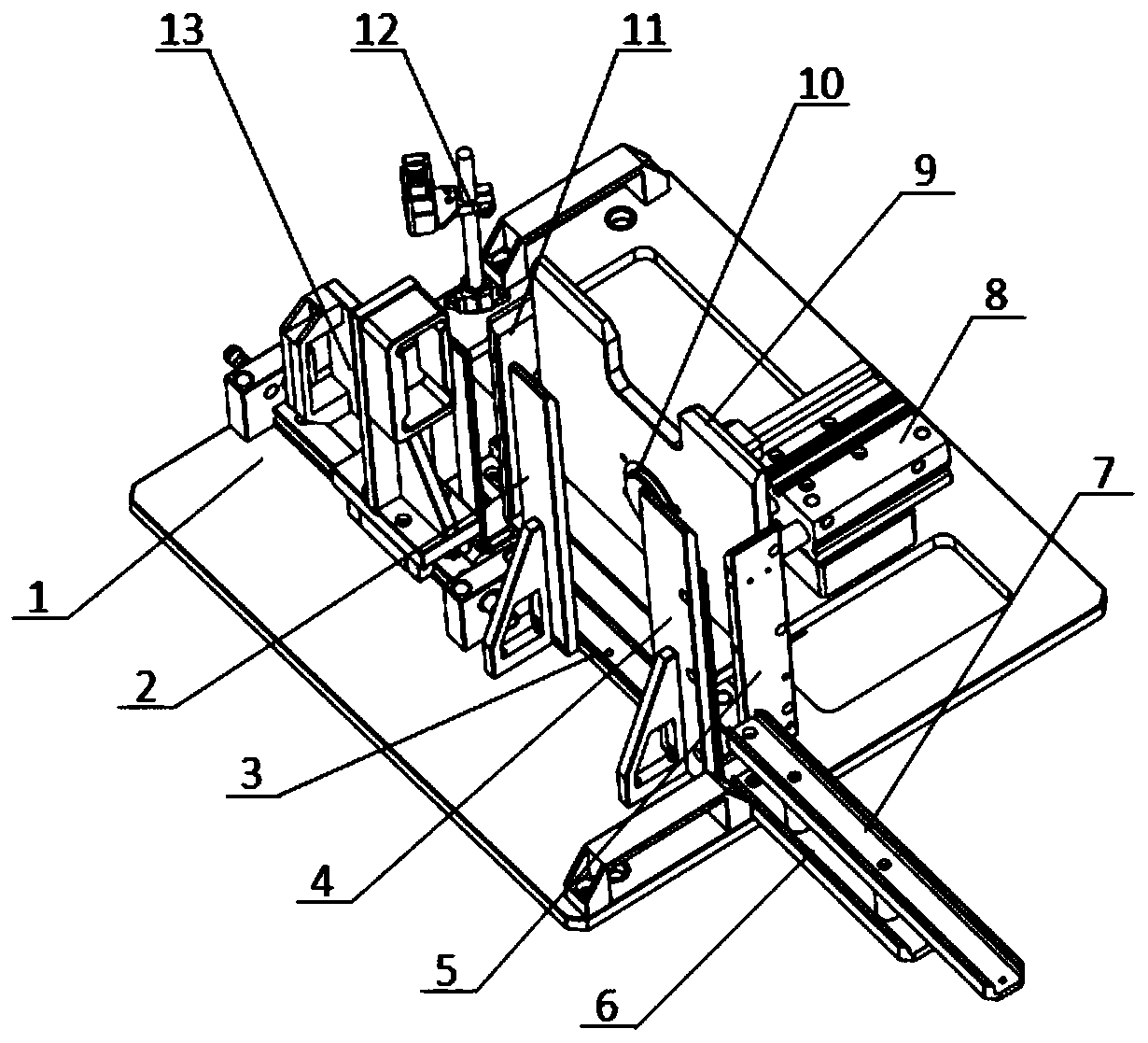
[0037] Such as figure 2 As shown, an evaporator assembly core sponge assembly device of the present invention is used to paste the core sponge 0.5 on the evaporator core 0.1, including a bottom plate 1 and a bottom plate 1 for limiting and supporting evaporation The limit support mechanism of the device core body 0.1.

[0038] In this implementation, the limit support mechanism includes a front...


PUM


Abstract

The invention relates to an assembling device for a core sponge of an evaporator assembly. The assembling device for the core sponge comprises a bottom plate and a limiting and supporting mechanism. The limiting and supporting mechanism comprises a front supporting plate, a rear supporting plate, a left supporting plate, a right supporting plate and a lower supporting plate; a gap for installationof the core sponge is formed between the front supporting plate and the right supporting plate, and the gap is provided with a first sponge bed plate where the core sponge is placed; the left supporting plate is provided with a gap for installation of the core sponge; and the rear supporting plate is provided with a locking mechanism for locking an evaporator core. The bottom plate is provided with the limiting and supporting mechanism to limit and support the evaporator core, the rear supporting plate is provided with the locking mechanism to lock the evaporator core, the gaps for installation of the core sponge are formed between the front supporting plate and the rear supporting plate and on the left supporting plate respectively, and sponge bed plates limit and support the core sponge. The above structure guarantees that the core sponge can be accurately and efficiently assembled on the evaporator core.

Description

technical field [0001] The invention relates to the field of automobile cooling systems, in particular to an evaporator assembly core sponge assembly device. Background technique [0002] Evaporator assembly (such as figure 1 ) consists of evaporator core 0.1, high pressure pipe 0.2, low pressure pipe 0.3, expansion valve 0.4 and core sponge 0.5. Among them, the high-pressure pipe 0.2 and the low-pressure pipe 0.3 are welded on the evaporator core 0.1 by brazing, the expansion valve 0.4 is installed on the high-pressure pipe 0.2 and the low-pressure pipe 0.3, and the core sponge 0.5 is pasted on the evaporator core 0.1. [0003] Among them, the core sponge 0.5 is pasted on the evaporator core 0.1. The main points of assembly are: different sizes and shapes of the evaporator core 0.1, high pressure 0.2, low pressure pipe 0.3, expansion valve 0.4 and core sponge 0.5 can form different models. The evaporator assembly requires error-proofing of the evaporator model; the expans...

Claims


Application Information

Patent Timeline
IPC IPC(8): B25B27/00B25B11/02G01M13/00G01M13/003G01V9/00
CPCB25B11/02B25B27/00G01M13/00G01M13/003G01V9/00
Inventor 张志刚胡文生曾志辉聂永红都英
Owner DONGFENG BEHR THERMAL SYST
Why Eureka
Try Eureka