
Loading machine and loading method

A feeding machine and material technology, which is applied in the field of feeding machines, can solve the problems of low assembly efficiency of backlight and low yield rate, etc., and achieve the effect of good use effect, high yield rate, and precise assembly position of materials

Pending Publication Date: 2020-02-28
SHENZHEN WEIHONGKE TECH
View PDF0 Cites 3 Cited by
  • Summary
  • Abstract
  • Description
  • Claims
  • Application Information

AI Technical Summary

Problems solved by technology

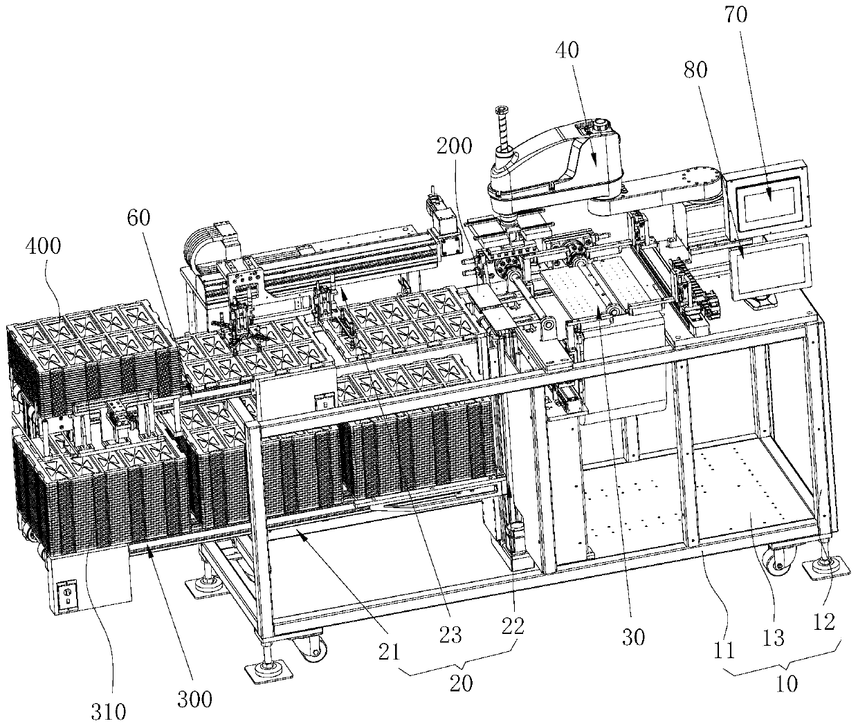
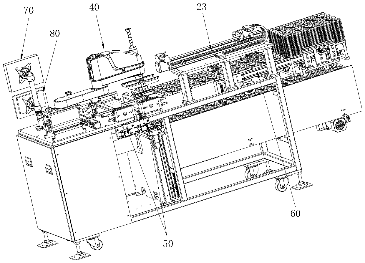
[0003] The purpose of the present invention is to provide a loading machine to solve the technical problems of low assembly efficiency and low yield of backlight caused by manual loading of backplanes in the prior art

Method used


Image

  • Loading machine and loading method
  • Loading machine and loading method
  • Loading machine and loading method

Examples


Embodiment Construction

[0046] In order to make the technical problems, technical solutions and beneficial effects to be solved by the present invention clearer, the present invention will be further described in detail below in conjunction with the accompanying drawings and embodiments. It should be understood that the specific embodiments described here are only used to explain the present invention, not to limit the present invention.

[0047] It should be noted that when an element is referred to as being “fixed” or “disposed on” another element, it may be directly on the other element or be indirectly on the other element. When an element is referred to as being "connected to" another element, it can be directly connected to the other element or indirectly connected to the other element.

[0048] It is to be understood that the terms "length", "width", "top", "bottom", "front", "rear", "left", "right", "vertical", "horizontal", "top" , "bottom", "inner", "outer" and other indicated orientations...


PUM


Abstract

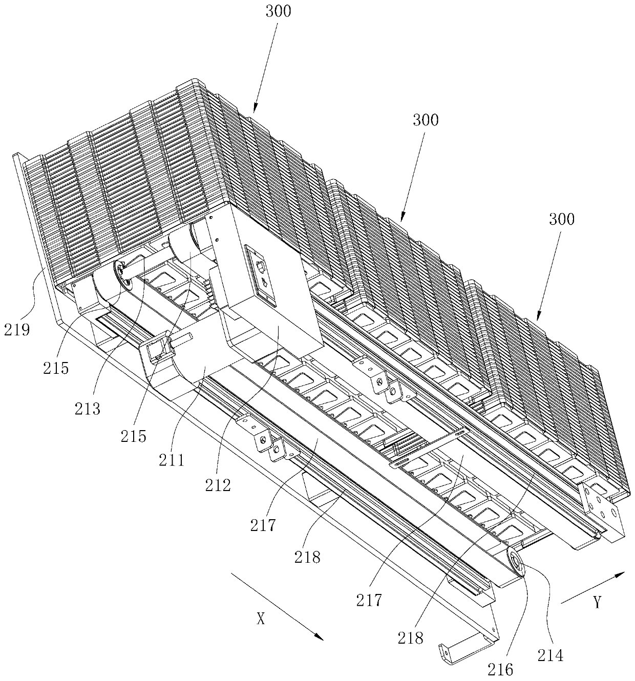
The invention provides a loading machine. The loading machine comprises a loading device, a dust removal device, a material transfer device, a positioning device and a control device, wherein the control device is electrically connected to the loading device, the dust removal device, the material transfer device and the positioning device separately; the loading device is used for conveying materials to the dust removal device; the dust removal device is used for cleaning dust on the materials; the material transfer device is used for transferring the materials cleaned by the dust removal device to a follow-up assembly process; the positioning device is used for positioning and calibrating materials on the transfer device; and the control device is used for controlling a working sequence of the loading device, the dust removal device, the material transfer device and the positioning device. The invention further provides a loading method which is used for loading. The loading machine provided by the invention loads a back plate, so that the back plate can be automatically loaded, and therefore, a backlight source assembly effect is good, dust-removal and positioning can be performed simultaneously, and the backlight source yield is guaranteed to be high.

Description

technical field [0001] The invention belongs to the technical field of backlight assembly, and more specifically relates to a feeding machine and a feeding method. Background technique [0002] The backlight is mainly composed of a light source, a light guide plate, an optical diaphragm, a backplane, and a plastic frame. Due to the complex structure of the backlight, its assembly process is relatively cumbersome. At present, there are assembly machines for assembling the light source, light guide plate, optical film, backplane and plastic frame into a backlight. However, when the assembly machine is assembling, the backplane is manually loaded. Manual loading not only greatly affects the assembly efficiency of the backlight, but also cannot be accurately positioned by manual loading, resulting in unclear assembly positions of the backplane and low yield. . Here, during the processing of the backplane, dust is likely to be generated, and after assembly, the entire backlight...

Claims


Application Information

Patent Timeline
Patent Type & Authority Applications(China)
IPC IPC(8): B65G47/90
CPCB65G47/902
Inventor 姜光泽姜文浩李春桥
Owner SHENZHEN WEIHONGKE TECH
Learn More