Pile cap for single pile bearing capacity detection of CFG pile and using method thereof

A technology of bearing capacity and single pile, which is applied in the test of sheet pile wall, foundation structure, construction, etc., can solve the problems of long detection period, inconvenience, and influence on the construction period, and achieve the goal of simple structure, low price, and reduced construction cost Effect

Inactive Publication Date: 2020-02-28
CHINA MCC20 GRP CORP
View PDF3 Cites 2 Cited by
  • Summary
  • Abstract
  • Description
  • Claims
  • Application Information

AI Technical Summary

Problems solved by technology

Therefore, the grouting material pile cap of this method still needs maintenance time, and there is also the problem that the detection cycle is long, which affects the construction period
[0005] Therefore there is above-mentioned inconvenience and problem in the pile cap of known CFG pile

Method used


Image

  • Pile cap for single pile bearing capacity detection of CFG pile and using method thereof
  • Pile cap for single pile bearing capacity detection of CFG pile and using method thereof

Examples


Embodiment 1

[0035] The pile cap used for testing the bearing capacity of a single pile of a CFG pile according to the invention is used for bearing a CFG pile whose bearing capacity of a single pile is ≤ 1000KN, and includes a steel casing and a steel plate.

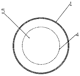
[0036] see now figure 1 , figure 1 It is a structural schematic diagram of a pile cap according to an embodiment of the present invention. As shown in the figure, the steel casing is a circular hollow steel pipe matching the shape of the end of the CFG pile. The steel pipe can be placed on the end of the CFG pile to form a pile cap; Sand, the fine sand inside the steel pipe is close to the outside of the CFG pile end.

[0037] The steel plate is a circular steel plate.

[0038] Wherein: a round steel plate is placed in the center of the fine sand top of the upper opening of the steel pipe. The material of the steel pipe is a 10mm thick steel plate. The distance between the inner wall 2 around the steel pipe and the outer side o...

Embodiment 2

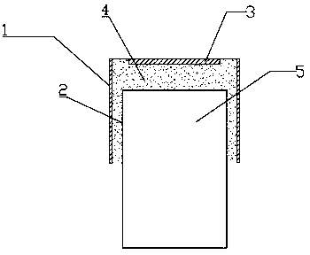
[0040] figure 2 It is a schematic diagram of the use state of the pile cap of the embodiment of the present invention. The using method of the pile cap that is used for the single pile bearing capacity detection of CFG pile of the present invention may further comprise the steps:

[0041] a. The CFG pile to be tested is cut off;

[0042] b. The steel pipe is placed at the end of the CFG pile;

[0043] c. Fill the contact part between the steel pipe and the CFG pile with fine sand, place a 20mm thick steel plate in the center on the top of the fine sand, and the distance between the steel plate and the pile top is 50~100mm;

[0044] d. Check the verticality of the steel pipe and the flatness of the fine sand on the top of the steel pipe and the flatness of the steel plate, set up the testing equipment and start the pile inspection.

[0045] 8. The method of using a pile cap for single pile bearing capacity detection of a CFG pile as claimed in claim 1, wherein the steel pip...


PUM


Abstract

The invention relates to a pile cap for single pile bearing capacity detection of a CFG pile. The pipe cap is used for bearing the CFG pile with a single pile bearing capacity of less than or equal to1000 KN. The pile cap comprises a steel protection barrel and a steel plate, and is characterized in that the steel protection barrel is a round hollow steel pipe matched with the end head of the CFGpile, and the steel pipe can movably sleeve the end head of the CFG pile to form the pile cap; the inner wall of the periphery of the hollow steel pipe abuts against the outer side of the end head ofthe CFG pile, and is filled with fine sand in the middle; the steel plate is a circular steel plate; and the round steel plate is centrally placed on the top of the fine sand on the upper opening ofthe steel pipe. The pile cap for the single pile bearing capacity detection of the CFG pile has the advantages that the pile cap is simple in structure, convenient to manufacture, safe and reliable indetection engineering quality, the pile inspection period is greatly shortened, and thus the construction total period is reduced, the material price of the pile cap is low, and the pile cap can be reused, and the construction cost is reduced.

Description

technical field [0001] The invention relates to a pile cap of a CFG pile, in particular to a pile cap used for testing the bearing capacity of a single pile of a CFG pile and a using method thereof. Background technique [0002] CFG piles are poured with plain concrete, and the CFG pile head is likely to crack or break when testing the bearing capacity of a single CFG pile, which may easily cause unqualified CFG pile test results and affect the quality of CFG piles. [0003] Therefore, when testing the bearing capacity of a CFG pile single pile, the pile head takes strengthening measures. One is to press the pile cap reinforcement cage into the pile head after the concrete pouring of the pile body is completed, but the construction of pressing the reinforcement cage is difficult; the other is to press the reinforcement cage into the pile head. After the concrete strength of the pile body is reached, the pile is cut to make a pile cap again. This method requires maintenance t...

Claims


Application Information

Patent Timeline
Patent Type & Authority Applications(China)
IPC IPC(8): E02D33/00E02D5/72
CPCE02D5/72E02D33/00
Inventor 黄升杜泽军符胜军孙嵩嵩薛亮亮吴化斌余学强
Owner CHINA MCC20 GRP CORP
Why Eureka
Try Eureka