
Furnace bottom structure of regenerative pusher type reheating furnace

A furnace bottom structure and heating furnace technology, which is applied to the furnace bottom, lighting and heating equipment, furnaces, etc., can solve the problems of low safety, increased concrete temperature stress, high investment, etc., and achieve the effect of avoiding overheating damage

Pending Publication Date: 2020-02-28
MCC CAPITAL ENGINEERING & RESEARCH
View PDF0 Cites 1 Cited by
  • Summary
  • Abstract
  • Description
  • Claims
  • Application Information

AI Technical Summary

Problems solved by technology

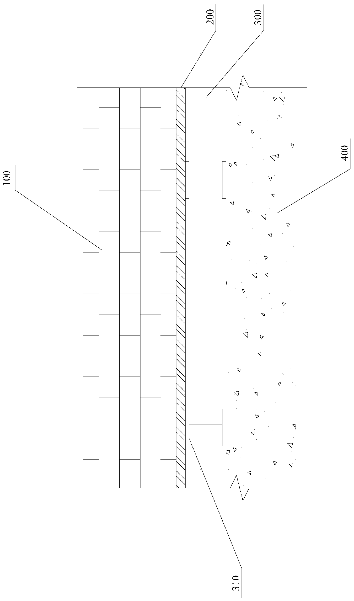
Although this furnace bottom structure is easy to install, in actual production, it is difficult to be found when the refractory brick insulation layer 100 in the furnace bottom structure is burned through. The furnace bottom steel plate 200 will be rapidly deformed, endangering the safety of the steel structure of the furnace body; when the situation is more serious, the strength of the steel bars in the heat-resistant reinforced concrete support structure 400 will also decrease sharply due to the temperature rise, and the temperature stress of the concrete will increase sharply, resulting in the destruction of the furnace bottom structure
Once the heat-resistant reinforced concrete support structure 400 of the furnace bottom structure of the heating furnace is damaged, it will be difficult to repair, the investment will be high, and the safety degree will be low. Generally, it can only be solved by rebuilding it in a different place

Method used


Image

  • Furnace bottom structure of regenerative pusher type reheating furnace
  • Furnace bottom structure of regenerative pusher type reheating furnace

Examples


Embodiment Construction

[0033] In order to have a clearer understanding of the technical solutions, objectives and effects of the present invention, the specific implementation manners of the present invention will now be described with reference to the accompanying drawings.

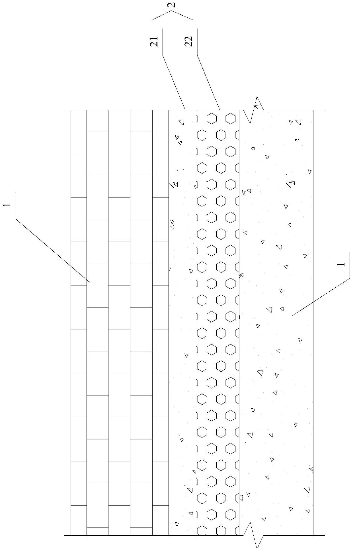
[0034] Such as figure 2 As shown, the present invention provides a furnace bottom structure of a regenerative pusher heating furnace, wherein the furnace bottom structure of a regenerative pusher heating furnace includes a refractory insulation layer 1 and a heat insulation structure 2 from top to bottom And the support structure 3, the heat insulation structure 2 is a solid structure, the upper surface of the heat insulation structure 2 is connected with the lower surface of the refractory insulation layer 1, and the lower surface of the heat insulation structure 2 is connected with the upper surface of the support structure 3. The furnace bottom structure of the regenerative push steel heating furnace provided by the presen...


PUM

PropertyMeasurementUnit
Heat resistance temperatureaaaaaaaaaa
Densityaaaaaaaaaa
Heat resistance temperatureaaaaaaaaaa

Abstract

The invention provides a furnace bottom structure of a regenerative pusher type reheating furnace. The furnace bottom structure of the regenerative pusher type reheating furnace comprises a refractoryheat preserving layer, a heat insulating structure and a supporting structure from top to bottom in sequence; the heat insulating structure is of a solid structure; the upper surface of the heat insulating structure is connected with the lower surface of the refractory heat preserving layer; and the lower surface of the heat insulating structure is connected with the upper surface of the supporting structure. According to the furnace bottom structure of the regenerative pusher type reheating furnace provided by the invention, a furnace bottom steel plate in the furnace bottom structure in theprior art is cancelled, so that the situation that a furnace body steel structure is damaged because of the deformation of the furnace bottom steel plate when the refractory heat preserving layer isburnt through is avoided fundamentally; meanwhile, the heat insulating structure of the solid structure is arranged between the refractory heat preserving layer and the supporting structure, so that the supporting structure can be effectively subjected to heat insulating protection through the heat insulating structure when the refractory heat preserving layer is burnt through; and therefore, thesituation of overheating damage of the supporting structure is effectively avoided.

Description

technical field [0001] The invention relates to the technical field of metallurgical heating equipment, in particular to a furnace bottom structure of a regenerative pusher heating furnace. Background technique [0002] The pusher type heating furnace is a common structure in metallurgical industry projects. When in use, the steel billet is pushed into the heating furnace by the steel pusher, and the billet slides on the slide rail supported by the water-cooled pipe, and the upper and lower sides of the billet can be heated. . [0003] At present, the furnace bottom structure of the heating furnace is composed of a refractory brick insulation layer 100, a furnace bottom steel plate 200, an air insulation layer 300 formed by a furnace bottom overhead steel beam 310, and a heat-resistant reinforced concrete support structure 400 from top to bottom, such as figure 1 shown. Although this furnace bottom structure is easy to install, in actual production, it is difficult to be f...

Claims


Application Information

Patent Timeline
IPC IPC(8): F27B17/00F27D1/00
CPCF27B17/00F27D1/0043
Inventor 刘兆强荣哲刘志侠孙衍法
Owner MCC CAPITAL ENGINEERING & RESEARCH
Learn More