Modulation device and method of optical frequency with arbitrary waveform

An arbitrary waveform and acousto-optic modulator technology, which is applied in the direction of measuring devices, optics, nonlinear optics, etc., can solve the problems that the standard laser vibrometer cannot completely solve the measurement traceability, the stability is not as good as the vibrometer, etc., and achieve high measurement Accuracy and stability, wide frequency range, effect of enhanced stability

Active Publication Date: 2020-02-28
BEIJING CHANGCHENG INST OF METROLOGY & MEASUREMENT AVIATION IND CORP OF CHINA
View PDF20 Cites 1 Cited by
  • Summary
  • Abstract
  • Description
  • Claims
  • Application Information

AI Technical Summary

Problems solved by technology

[0003] Aiming at the main problems in the measurement calibration and performance evaluation of the laser vibrometer, which are limited by the mechanical movement of the vibrating table, the technical parameters cannot completely cover the range of the vibrometer and the stability is not as good as that of the vibrometer, and the standard laser vibrometer traceability The problem that cannot be completely solved, the technical problem to be solved by an optical frequency modulation excitation device and method disclosed in the present invention is: use optical frequency modulation to generate arbitrary waveform excitation of analog vibration, and can be used as an evaluation of the characteristics of the laser vibrometer The excitation source avoids being limited by the technical parameters of the vibration table and other mechanical movements, which cannot completely cover the range of the vibrometer, improves the stability of the vibrometer, and realizes the traceability of the standard laser vibrometer.

Method used


Image

  • Modulation device and method of optical frequency with arbitrary waveform

Examples


Embodiment

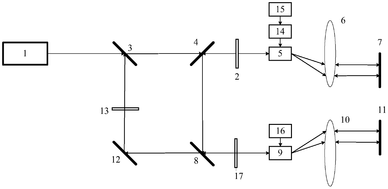
[0023] like figure 1 As shown, an arbitrary waveform optical frequency modulation device disclosed in this embodiment consists of a laser vibrometer 1, a first λ / 2 wave plate 2, a second λ / 2 wave plate 13, and a third λ / 2 wave plate 17. First polarizing beam splitter 3, second polarizing beam splitter 4, third polarizing beam splitter 8, first lens 6, second lens 10, first plane mirror 7, second plane mirror 11, third plane The reflecting mirror 12 , the first acousto-optic modulator 5 , the second acousto-optic modulator 9 , the FM signal source 14 , the arbitrary wave generator 15 , and the sinusoidal signal source 16 are composed.

[0024] The laser light generated by the laser vibrometer 1 passes through the first polarizing beam splitter 3, the second polarizing beam splitter 4, and the first λ / 2 wave plate 2, and reaches the first acousto-optic modulator 5, and the arbitrary wave generator 15 generates the generated laser beam. The desired arbitrary waveform modulation ...


PUM


Abstract

The invention discloses an optical frequency modulation type excitation device and method, and belongs to the technical field of photoelectric measurement. The device mainly comprises a laser vibration meter, a first [lambda] / 2 wave plate, a second [lambda] / 2 wave plate, a third [lambda] / 2 wave plate, a first polarizing beam splitter, a second polarizing beam splitter, a third polarizing beam splitter, a first lens, a second lens, a first plane mirror, a second plane mirror, a third plane mirror, a first acoustic optical modulator, a second acoustic optical modulator, an FM signal source, an arbitrary wave generator and a sinusoidal signal source. Any waveform excitation for simulating vibration is generated in an optical frequency modulation mode and can serve as an excitation source forcharacteristic evaluation of the laser vibration meter, the problem that technical parameters of mechanical movement such as a vibration table cannot completely cover the measuring range of the vibration meter is solved, the stability of the excitation source is improved, and metering traceability of the standard laser vibration meter is achieved. The optical frequency modulation type excitation device and method have the advantages of the faster rise time, the wider frequency range, the larger amplitude range and the more complex and changeable waveform characteristics.

Description

technical field [0001] The invention relates to an arbitrary waveform optical frequency modulation device and method, belonging to the technical field of photoelectric measurement. Background technique [0002] The laser vibrometer is a general-purpose, basic vibration and shock measuring instrument with high precision, non-contact, and no additional interference and impact on the measured object. Its measurement calibration and performance evaluation have always been difficult problems in the industry. The main reasons are: 1) Its excitation is motion magnitude (displacement, velocity, acceleration), and the measurement principle used is performed by the laser Doppler effect, which needs to perceive physical motion through optical frequency changes, and the output is based on electrical signal data. The results are given in the form, involving different aspects such as mechanical movement, optical frequency control, electronic measurement and so on. 2) Since the frequency ...

Claims


Application Information

Patent Timeline
Patent Type & Authority Applications(China)
IPC IPC(8): G01H9/00G02F1/11
CPCG01H9/00G02F1/11
Inventor 梁志国朱振宇
Owner BEIJING CHANGCHENG INST OF METROLOGY & MEASUREMENT AVIATION IND CORP OF CHINA
Why Eureka
Try Eureka