One-dimensional closed-loop micro-nano vibration table

A vibrating table, micro-nano technology, used in fluids, instruments, measuring devices, etc. that use vibration, can solve problems such as inability to meet high-precision sensors, inability to generate vibration, time-consuming and labor-intensive adjustment, and achieve simple structure and high structural stability. , the effect of a large amplitude range

Active Publication Date: 2019-02-12
HEFEI UNIV OF TECH
View PDF5 Cites 0 Cited by
  • Summary
  • Abstract
  • Description
  • Claims
  • Application Information

AI Technical Summary

Problems solved by technology

[0004] At present, the most commonly used vibrating table is the electromagnetic vibrating table, which uses electromagnets as the power to convert electrical energy into mechanical kinetic energy, which can generate high-frequency and large-amplitude vibrations, and the noise generated during use is relatively large; electromagnetic vibrators Most of the assembly methods are connected by leaf springs. During use, the number of spring pieces needs to be adjusted according to the size of the product. The adjustment is time-consuming and laborious, and the vibration accuracy is low. It can only provide vibrations with an accuracy of about 1 micron, and cannot produce vibrations as low as Nanoscale vibration cannot meet the needs of high-precision sensor calibration and testing

Method used


Image

  • One-dimensional closed-loop micro-nano vibration table
  • One-dimensional closed-loop micro-nano vibration table
  • One-dimensional closed-loop micro-nano vibration table

Examples


Embodiment Construction

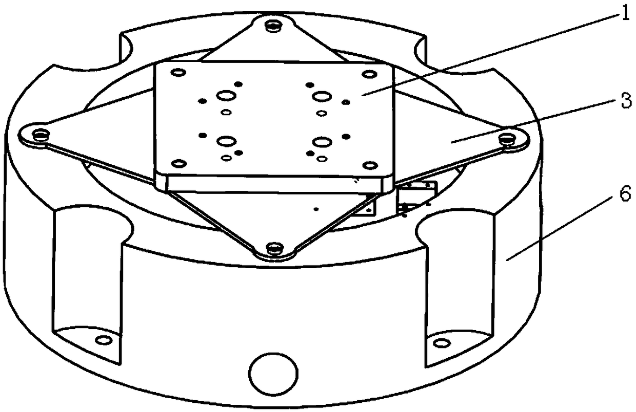
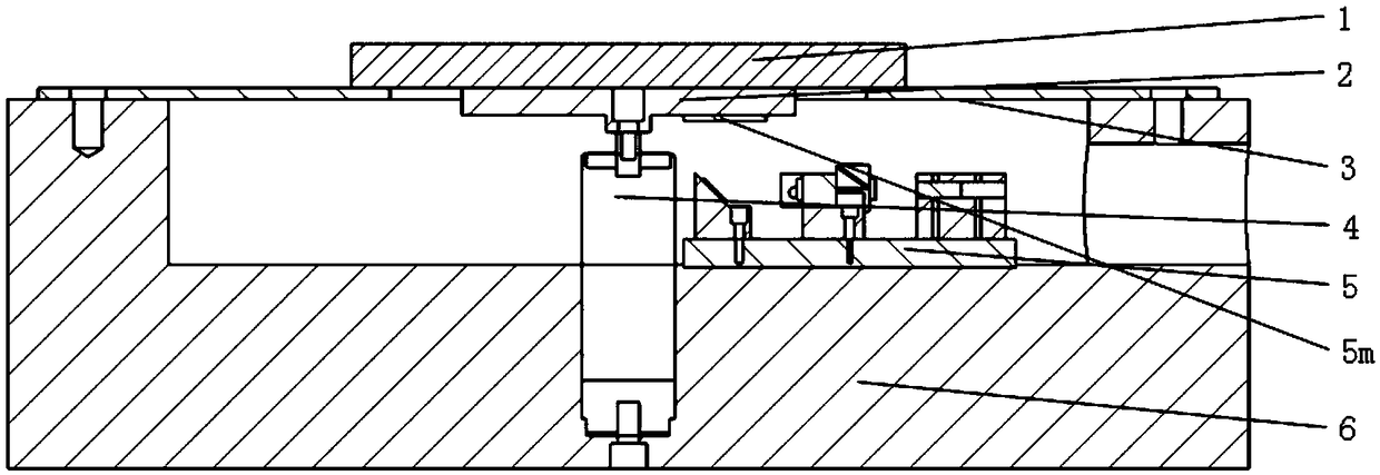
[0027] see figure 2 and image 3 , the structural form of the one-dimensional closed-loop micro-nano vibrating table in the present embodiment is: the beryllium copper reed 3 is used as the elastic component, the center of the beryllium copper reed 3 is a circular cavity, and the beryllium copper reed 3 utilizes a cross distribution The reed screws are fixed on the upper surface of the base 6; the worktable 1 is placed on the upper surface of the beryllium copper reed 3, and fixed on the beryllium copper reed 3 by table screws distributed in a cross to form an elastic structure, so that the worktable 1 The limit is obtained on the horizontal plane, and vibration displacement can be formed in the vertical direction; the shape and thickness of the beryllium copper reed 3 are optimized by ANSYS simulation to meet the application requirements.

[0028] Such as image 3 and Figure 4 As shown, the base 6 is a cylinder with a closed bottom and an open top, and a piezoelectric ce...


PUM


Abstract

The invention discloses a one-dimensional closed-loop micro-nano vibration table which is characterized in that by taking a beryllium copper reed as an elastic component, a table surface is arranged on the upper surface of the beryllium copper reed, thus an elastic structure is formed; the table surface can only generate vibration displacement in the vertical direction; an adapter board is arranged at the bottom surface of the table surface, and is in T-shaped connection with a displacement output head of a piezoelectric ceramic actuator; the piezoelectric ceramic actuator drives the table surface to move vertically through the adapter board; a motion state of the adapter board is detected in real time by employing a michelsons interferometer and acts as a detection signal; and a signal processing and control system outputs a control signal to the piezoelectric ceramic actuator according to the detection signal, thereby realizing closed-loop control of an experiment table. High-precision micro-nano vibration can be obtained, and the one-dimensional closed-loop micro-nano vibration table has the advantages that the amplitude and frequency ranges are wide, the output vibration repeatability is high, the cost is high, the assembly and adjustment are convenient, and the closed-loop control can be realized.

Description

technical field [0001] The invention relates to the field of micro-nano vibrating tables, more specifically to a vibrating table that can be used to test and calibrate micro-nano vibration sensors, and can generate high-precision micro-nano vibrations. Background technique [0002] In recent years, more and more precision measuring instruments have been designed and manufactured, such as micro-nano three-dimensional coordinate measuring machines, atomic force microscopes, and high-precision laser interferometers. When working, these instruments will be affected by various external disturbances, and low-frequency micro-vibration is one of the main factors. For example, low-frequency micro-vibrations caused by passing a car on the road, someone walking by, sound, etc. will interfere with the use of precision instruments. Therefore, it is necessary to develop a high-precision low-frequency micro-vibration measurement system. [0003] Precision measurement occasions put forwar...

Claims


Application Information

Patent Timeline
Patent Type & Authority Patents(China)
IPC IPC(8): B06B1/06G01H17/00
CPCB06B1/0655G01H17/00
Inventor 李瑞君雷英俊张连生范光照
Owner HEFEI UNIV OF TECH
Why Eureka
Try Eureka