Laser radar performance testing device and testing method

A technology of laser radar and testing equipment, which is applied in the direction of radio wave measurement systems and instruments, can solve the problems of lack of laser radar, testing methods and evaluation systems, and numerous and redundant laser radars, and achieve the effect of promoting development

Active Publication Date: 2020-02-28
63963 TROOP OF THE PLA
View PDF10 Cites 17 Cited by
  • Summary
  • Abstract
  • Description
  • Claims
  • Application Information

AI Technical Summary

Problems solved by technology

With the development of unmanned driving, more and more unmanned vehicles use lidar. The role of lidar for unman

Method used


Image

  • Laser radar performance testing device and testing method
  • Laser radar performance testing device and testing method
  • Laser radar performance testing device and testing method

Examples


Embodiment 1

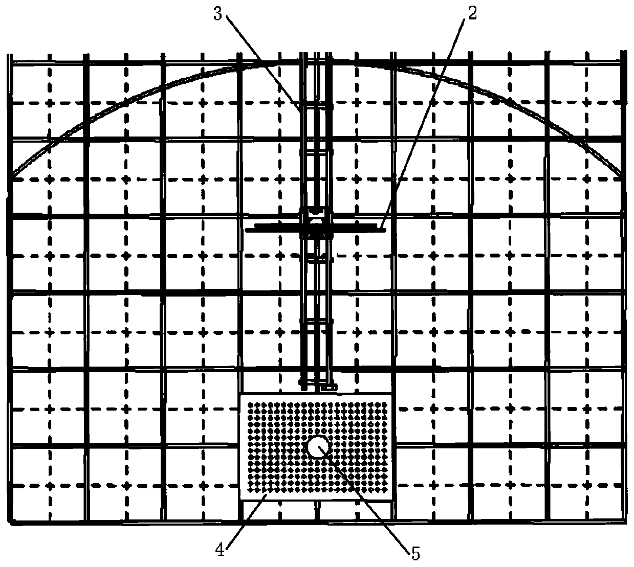
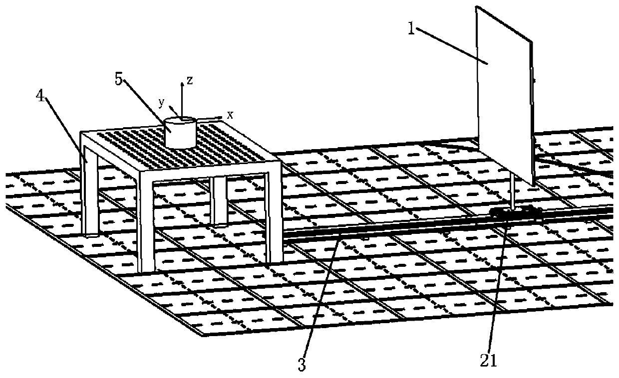
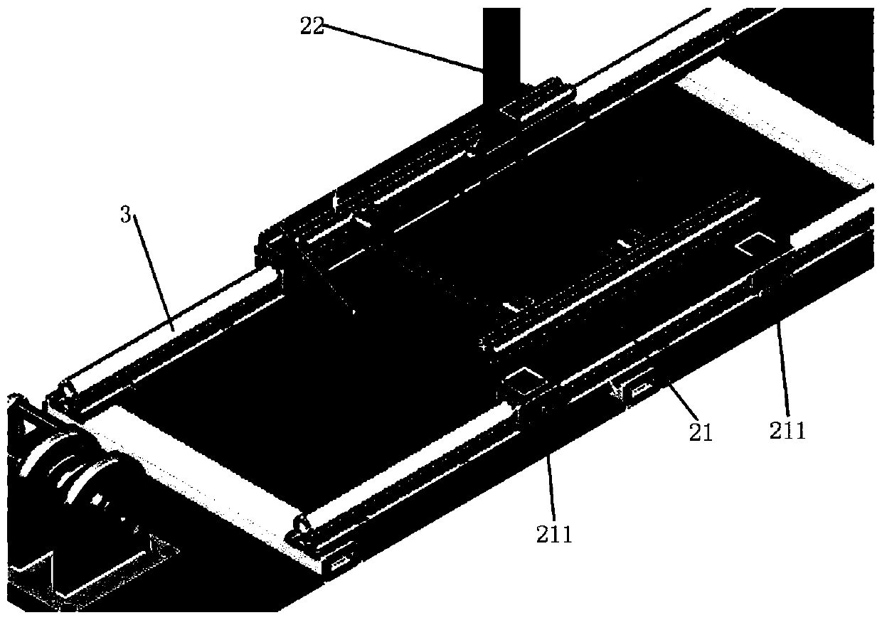
[0047] figure 1 It is a top view of the lidar performance testing device described in one embodiment of the present invention; figure 2 It is a structural schematic diagram of the lidar performance testing device described in one embodiment of the present invention; image 3 It is a schematic diagram of the connection between the target plate support and the linear guide rail in one embodiment of the present invention.

[0048] Such as Figure 1 to Figure 3 As shown, the lidar performance testing device in this embodiment includes: a target plate 1, a target plate support 2, a linear guide rail 3, an optical platform 4 and a testing machine (not shown in the figure). Wherein, the target plate 1 is used to withstand the laser light emitted by the lidar. In this embodiment, the target plate 1 is a rectangular plate, and its size is different when different performance tests are performed. The target plate support 2 includes a mobile platform 21, a telescopic rod 22 and a tel...

Embodiment 2

[0054] Figure 4 It is a structural schematic diagram of the laser radar performance testing device in one embodiment of the present invention when testing the multiple echo capability of the laser radar.

[0055] Please refer to Figure 4 In this embodiment, a laser radar performance test method is provided, for testing the echo capability of the laser radar, the laser radar performance test device described in embodiment 1 is adopted, and the test method includes the following steps:

[0056] Step S11, fixing the laser radar 5 to be tested on the optical platform 4, so that the positive direction of the X-axis of the laser radar 5 points to the target plate support 2, and the X-axis of the laser radar 5 is parallel to the linear guide rail 3 , and then connect the lidar 5 with the testing machine.

[0057] Step S12, installing three above-mentioned target plate supports 2 on the linear guide rail.

[0058] Step S13, install target plates 1 with the same size and the same ...

Embodiment 3

[0061] Figure 5 It is a structural schematic diagram of the laser radar performance testing device in one embodiment of the present invention when testing the effective ranging range of the laser radar. The direction indicated by the arrow in the figure is the moving direction of the target plate support 2, and the figure shows the movement state of the target plate support 2 when testing the minimum measurement distance of the laser radar.

[0062] Please refer to Figure 5 , In this embodiment, a method for testing laser radar performance is provided, which is used to test the effective ranging range of laser radar, including the minimum measurement distance and the maximum measurement distance, using the laser radar performance test device described in embodiment 1 , the test method comprises the steps of:

[0063] Step S21, fixing the laser radar 5 to be tested on the optical platform 4, so that the positive direction of the X-axis of the laser radar 5 points to the tar...


PUM


Abstract

The invention discloses a laser radar performance testing device, and the device comprises a target plate which is used for bearing laser emitted by a laser radar; a target plate bracket, wherein a telescopic clamp is arranged on the target plate bracket and the target plate bracket is used for fixing the target plate; a linear guide rail, wherein the target plate bracket is arranged on the linearguide rail and can slide along the linear guide rail; an optical platform which is arranged at one end of the linear guide rail and is used for fixing a tested radar; and a test machine which is usedfor analyzing the test data. In addition, the invention also discloses a method for testing the echo capability, the effective range finding range, the range finding precision, the horizontal angle resolution, the vertical field angle, the vertical angle resolution and the range finding value consistency of the laser radar by using the device. Through the laser radar testing device, the key performance parameters of the tested laser radar can be effectively evaluated and reflected.

Description

technical field [0001] The invention relates to the technical field of radar performance testing, in particular to a laser radar performance testing device and a method for testing laser radar performance using the device. Background technique [0002] The laser scanning method is not only the main way to obtain three-dimensional geographic information in the military, but also the data obtained through this way are also widely used in resource exploration, urban planning, agricultural development, water conservancy engineering, land use, environmental monitoring, transportation and communication, Earthquake prevention and disaster reduction and national key construction projects provide extremely important raw materials for national economy, social development and scientific research, and have achieved remarkable economic benefits, showing good application prospects. With the development of unmanned driving, more and more unmanned vehicles use lidar. The role of lidar for u...

Claims


Application Information

Patent Timeline
IPC IPC(8): G01S7/497
CPCG01S7/497
Inventor 孔国杰陶溢余彪梁华为龚建伟张家斌王利军朱祺闫磊孙涛吴新明尹宏俊
Owner 63963 TROOP OF THE PLA
Why Eureka
Try Eureka