Optical lens

A technology of optical lens and optical imaging lens, which is applied in the field of optical lens, can solve the problems of poor distortion control, large volume, and low relative illumination, and achieve the effects of reducing temperature variation, good system stability, and overall system length

Pending Publication Date: 2020-02-28
XIAMEN LEADING OPTICS
View PDF0 Cites 2 Cited by
  • Summary
  • Abstract
  • Description
  • Claims
  • Application Information

AI Technical Summary

Problems solved by technology

[0003] However, the glass-plastic hybrid lenses currently on the market for 3D structured light projection still have the following shortcomings: 1. The focal length and resolution drift with temperature, which affects the final recognition accuracy; 2. Poor control of distortion, which affects the final recognition Accuracy; 3. Larger volume; 4. Relative illuminance is low, there is a gap with market demand, and it needs to be improved

Method used


Image

  • Optical lens
  • Optical lens
  • Optical lens

Examples


Embodiment 1

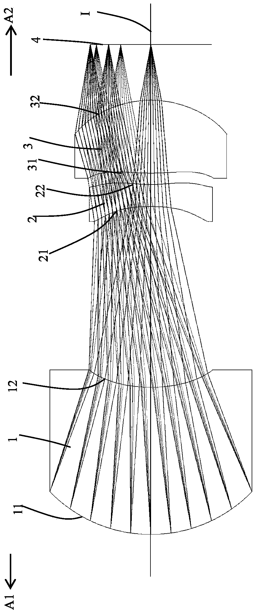
[0136] Such as figure 1 As shown, an optical lens is used to project light from a light source to an object through the optical lens. The direction toward the light source is the image side A2, and the direction toward the object is the object side A1. The optical lens is from the object The side A1 to the image side A2 sequentially include a diaphragm (not shown in the figure), a first lens 1, a second lens 2, a third lens 3, and a projection surface (ie, a light source) 4 along an optical axis I; the projection surface 4 emits The light from the third lens 3, the second lens 2, the first lens 1 and the diaphragm are projected onto the subject in sequence. The object side and an image side facing the image side A2 through which the imaging light passes.

[0137] The first lens 1 has a positive refractive power, the object side 11 of the first lens 1 is a convex surface, and the image side 12 of the first lens 1 is a concave surface; the second lens 2 has a negative refractiv...

Embodiment 2

[0162] Such as Figure 17 As shown, this embodiment and the embodiment 1 have the same concave-convex surface shape and refractive index of each lens, and only the optical parameters such as the radius of curvature of each lens surface and lens thickness are also different.

[0163] The detailed optical data of this specific embodiment are shown in Table 2-1.

[0164] Detailed optical data of Table 2-1 Example 2

[0165] surface Aperture radius (mm) Radius of curvature (mm) Thickness (mm) material Refractive index Dispersion coefficient focal length(mm) - subject surface 49.81 INF 450 - 0.88 INF 0.100 11 first lens 0.84 1.226 1.216 M-NBFD130 1.8061 40.7306 3.82 12 0.51 1.165 1.340 21 second lens 0.45 -1.839 0.241 ZEONEX_330R 1.5094 56.4745 -1.29 22 0.52 1.023 0.111 31 third lens 0.54 1.674 0.660 ZEONEX_T62R 1.5365 55.9807 1.25 32 0.61...

Embodiment 3

[0173] Such as Figure 33 As shown, this embodiment and the embodiment 1 have the same concave-convex surface shape and refractive index of each lens, and only the optical parameters such as the radius of curvature of each lens surface and lens thickness are also different.

[0174] The detailed optical data of this specific embodiment are shown in Table 3-1.

[0175] Detailed optical data of the third embodiment of table 3-1

[0176] surface Aperture radius (mm) Radius of curvature (mm) Thickness (mm) material Refractive index Dispersion coefficient focal length(mm) - subject surface 49.72 INF 450 - 0.88 INF 0.100 11 first lens 0.84 1.295 1.190 D-ZF93 2.0017 20.7054 4.06 12 0.49 1.066 1.392 21 second lens 0.46 -1.690 0.238 ZEONEX_330R 1.5094 56.4745 -1.40 22 0.52 1.266 0.111 31 third lens 0.55 1.536 0.619 ZEONEX_T62R 1.5365 55.9807 1.25 ...


PUM


Abstract

The invention relates to the technical field of lenses, and discloses an optical lens for projecting light rays to a measured object from a light source. The direction facing the light source is an image side, and the direction facing the measured object is an object side. The optical lens sequentially comprises a first lens, a second lens and a third lens along an optical axis from the object side to the image side. Each of the first lens, the second lens and the third lens comprises an object side surface and an image side surface, wherein the object side surface facing the object side allows imaging light rays to pass through, and the image side surface facing the image side also allows the imaging light rays to pass through. The first lens made of a glass material is a convex-concave lens with a positive refractive index. The second lens is a concave-concave lens with a negative refractive index. The third lens is a convex-convex lens with a positive refractive index. The second lens and the third lens are aspherical lenses made of plastic materials. The optical lens has the advantages of small temperature-dependent variation in focal length and image quality, high system stability, small distortion, high relative illumination and small system size.

Description

technical field [0001] The invention belongs to the technical field of lenses, in particular to an optical lens with good thermal stability. Background technique [0002] The basic principle of 3D structured light is to project light with certain structural characteristics onto the object to be photographed through a near-infrared laser, and then collect it with a special infrared camera. This kind of light with a certain structure will collect different image phase information due to different depth areas of the subject, and then convert this structure change into depth information through the computing unit to obtain a three-dimensional structure. The image is converted from the past two-dimensional space to the three-dimensional space, thus bringing a more real and clear perceptual experience. The projection lens used to project the array point light source emitted by the laser surface with a specific solid angle onto the surface of the object is a key link in the imagin...

Claims


Application Information

Patent Timeline
Patent Type & Authority Applications(China)
IPC IPC(8): G02B13/00G02B13/18G02B1/00G02B1/04
CPCG02B1/00G02B1/041G02B13/0035G02B13/18
Inventor 郑毅黄翔邦
Owner XIAMEN LEADING OPTICS
Why Eureka
Try Eureka