Novel circuit forming method

A circuit and circuit pattern technology, which is applied in the removal of conductive materials by chemical/electrolytic methods, printed circuits, and printed circuit manufacturing, etc., can solve the problems of high overall cost, affecting circuit etching, and chemical residue, and simplify the production process. steps, the effect of reducing the cost of labor and equipment

Inactive Publication Date: 2020-02-28
江苏上达半导体有限公司
View PDF7 Cites 2 Cited by
  • Summary
  • Abstract
  • Description
  • Claims
  • Application Information

AI Technical Summary

Problems solved by technology

[0004] 1. In the actual operation process of manual dry film sticking, there will be deviation, missed sticking, re-sticking, etc., which will cause waste of materials, increase production costs, and reduce the efficiency of operations;
[0005] 2. In order not to waste the base material, the products with the above errors will be reworked. During the rework process, the product quality will be adversely affected, and the final yield of the product may be affected;
[0006] 3. During the exposure process, there will be poor exposure due to insufficient energy, and there is also the possibility of rework, and the equipment used for exposure is also very expensive, and the overall cost is relatively high;
[0007] 4. At present, alkaline liquid is mostly used in development and etching. During the production process, the development process causes liquid residue, which affects the subsequent line etching and ultimately affects the overall yield of the product.

Method used


Image

  • Novel circuit forming method
  • Novel circuit forming method
  • Novel circuit forming method

Examples


Embodiment

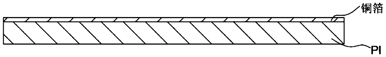
[0026] Such as Figure 1-4 As shown, the embodiment of the present invention provides a new method for forming a line, including the following steps:

[0027] S1. Pretreat the product base material;

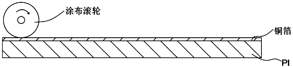
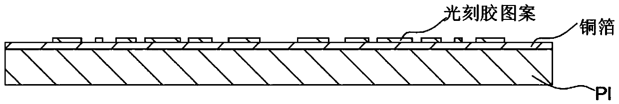
[0028] S2, using a coating roller to coat the photoresist on the pretreated substrate to obtain a product with a photoresist pattern;

[0029] S3, baking the product coated with the photoresist pattern to cure the photoresist;

[0030] S4. Etching the product with the photoresist pattern cured after baking, etching away the copper foil that is not covered by the photoresist, and then developing to remove the photoresist on the surface of the product to obtain the desired circuit pattern .

[0031] The coating roller used in step 2 is provided with a mask pattern corresponding to the circuit, and the pattern on the roller can be the pattern on the final product, or the pattern opposite to the pattern on the final product.

[0032] By using the method of roller coating pattern ...


PUM


Abstract

The invention provides a novel circuit forming method, and relates to the technical field of circuit forming. The new circuit forming method comprises the following steps: S1, pretreating a product substrate; S2, coating photoresist on the pre-treated substrate by using a coating roller to obtain a product with a photoresist pattern; S3, baking the product coated with the photoresist pattern to cure the photoresist; and S4, etching the baked product with the cured photoresist pattern to remove a copper foil which is not covered by the photoresist, and then, carrying out development to remove the photoresist on the surface of the product to obtain a required circuit pattern. According to the invention, the circuit board is manufactured by using a roller pattern coating method, so that the processes of exposure, development and the like are omitted, the original production process steps can be simplified, the labor and equipment costs are greatly reduced, adverse effects caused by manualoperation are avoided, the product quality can be ensured, and the production efficiency is improved.

Description

technical field [0001] The invention relates to the technical field of circuit forming, in particular to a new circuit forming method. Background technique [0002] With the development of industrial technology and the arrival of Industry 4.0, the automation of various manufacturing factories is getting higher and higher. For the circuit board industry, automation is mainly reflected in each process. Due to the intelligence of the equipment, each processing process tends to be intelligent. As far as several processes of circuit forming in the prior art circuit board processing are concerned, it is generally necessary to carry out Manually paste the dry film, expose, develop, etch the circuit, and then remove the dry film to expose the required circuit. [0003] Above traditional method has the following deficiencies: [0004] 1. In the actual operation process of manual dry film sticking, there will be deviation, missed sticking, re-sticking, etc., which will cause waste o...

Claims


Application Information

Patent Timeline
Patent Type & Authority Applications(China)
IPC IPC(8): H05K3/06
CPCH05K3/064H05K2203/0551
Inventor 徐世明王健孙彬沈洪李晓华
Owner 江苏上达半导体有限公司
Why Eureka
Try Eureka