Building concrete recycling equipment,

A concrete and equipment technology, applied in the field of construction concrete recycling equipment, can solve the problems of poor crushing effect, inability to adjust the size of fragments, and inability to adjust the crushing bite range, etc., to achieve good crushing effect and easy discharging.

Active Publication Date: 2020-03-06
王朝晖
View PDF13 Cites 7 Cited by
  • Summary
  • Abstract
  • Description
  • Claims
  • Application Information

AI Technical Summary

Problems solved by technology

[0002] In construction waste, reinforced concrete waste occupies a large proportion and needs to be crushed and decomposed. Traditional jaw crushing equipment cannot adjust the occlusal range of crushing and the size of fragments after crushing. The lower jaw plate is fixed and the crushing effect is not good. , this device solves the above problems

Method used


Image

  • Building concrete recycling equipment,
  • Building concrete recycling equipment,
  • Building concrete recycling equipment,

Examples


specific Embodiment approach 1

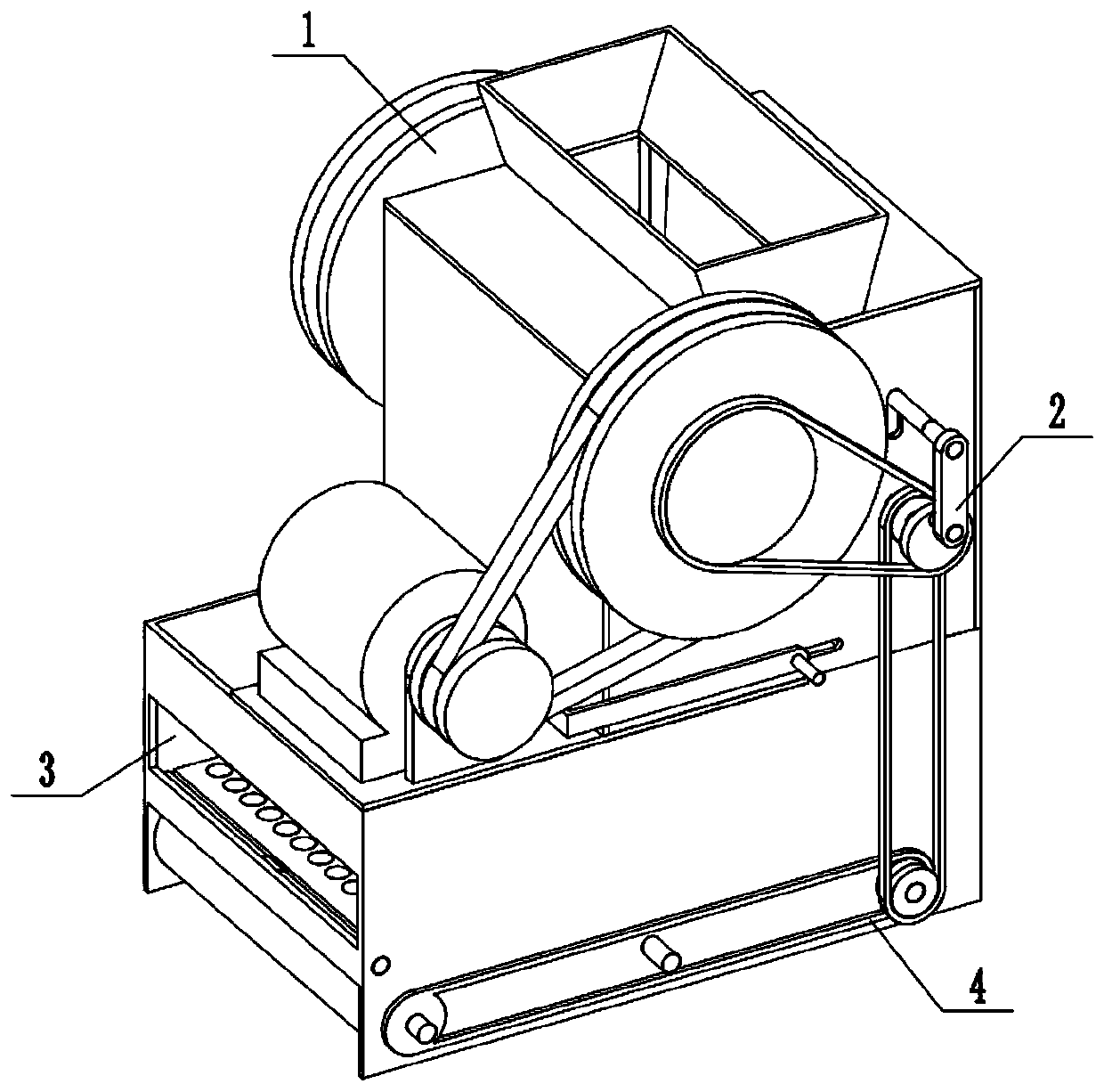
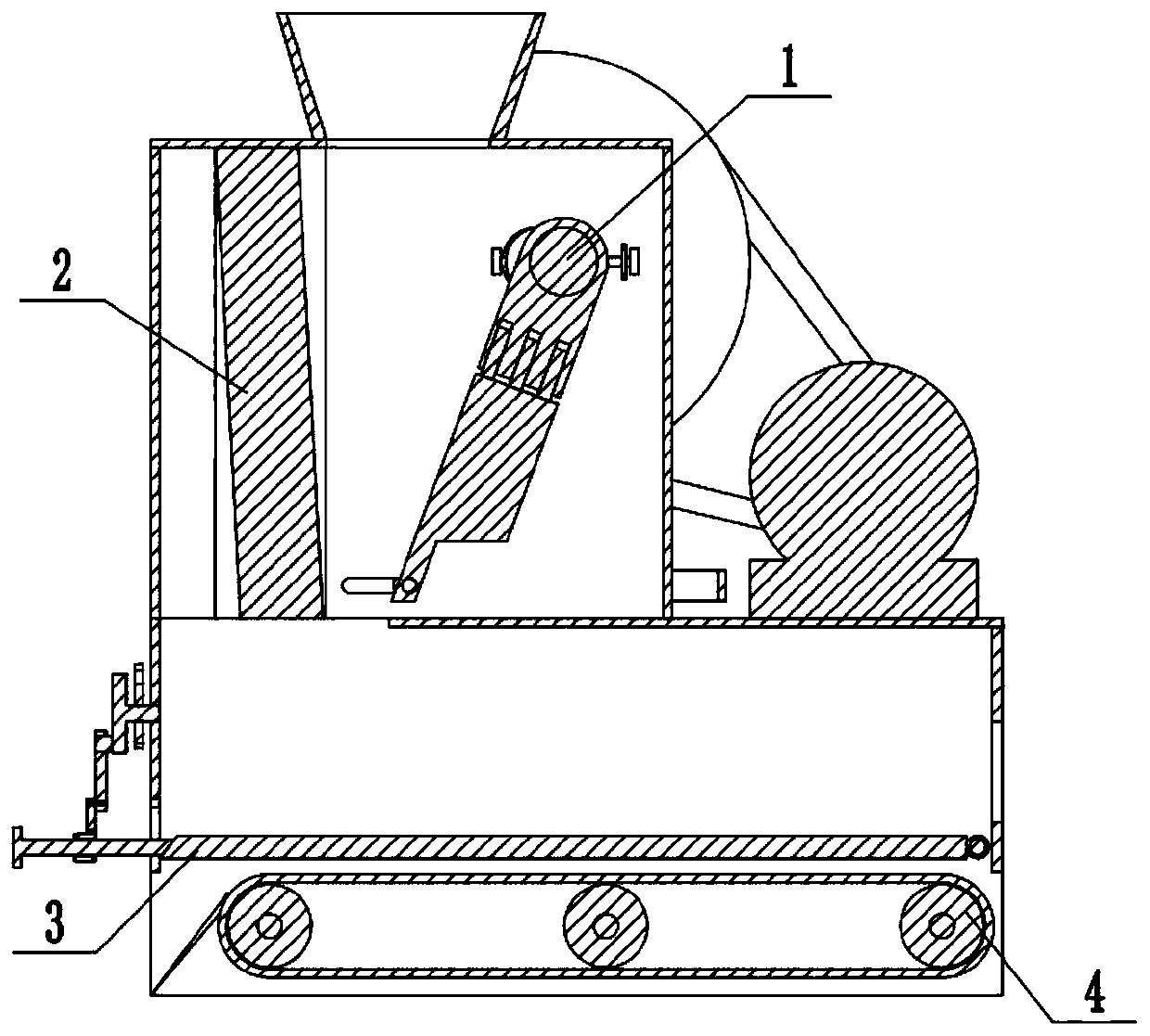
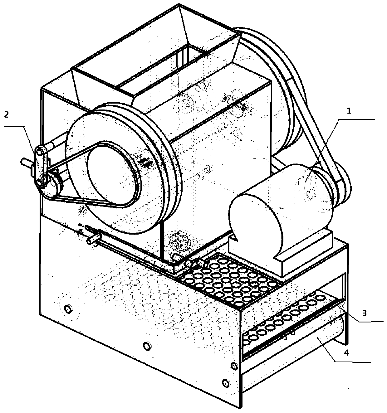
[0033] Combine below Figure 1-18 Embodiment, a kind of building concrete recycling equipment, including the upper jaw assembly 1, the lower jaw assembly 2, the separation assembly 3 and the conveying assembly 4, characterized in that: the upper jaw assembly 1 and the lower jaw assembly 2 are connected , the separation assembly 3 is connected to the upper jaw assembly 1, the separation assembly 3 is connected to the lower jaw assembly 2, the delivery assembly 4 is connected to the separation assembly 3, and the delivery assembly 4 is connected to the lower jaw assembly 2.

specific Embodiment approach 2

[0035] Combine below Figure 1-18 Embodiment, this embodiment will further explain Embodiment 1. The upper jaw assembly 1 includes a motor 1-1, a pulley I 1-2, a motor bracket 1-3, a V-belt 1-4, a pulley II 1-5, Bottom plate 1-6, side plate Ⅰ 1-7, side plate Ⅱ 1-8, upper plate 1-9, material inlet 1-10, counterweight wheel 1-11, shaft Ⅰ 1-12, shaft Ⅱ slide rail 1-13, Chute 1-14, shaft II 1-15, slider 1-16, adjustment handle 1-17, threaded shaft 1-18, slider limit block 1-19, ball 1-20, driven slider 1-21 , upper jaw plate Ⅰ1-22, upper jaw chute 1-23, upper jaw plate II 1-24, rotating shaft 1-25, rotating shaft chute 1-26, rotating shaft bracket 1-27, thread adjustment rod 1-28 and handle 1-29, Motor 1-1 is provided with motor shaft, and the motor shaft of motor 1-1 is connected with pulley Ⅰ1-2, and the motor shaft of motor 1-1 is connected with motor support 1-3 rotation, and motor support 1-3, motor 1- 1 are all connected with the bottom plate 1-6, the pulley Ⅰ1-2, the V-be...

specific Embodiment approach 3

[0037] Combine below Figure 1-18 Embodiment, this embodiment will further explain Embodiment 1. The lower jaw assembly 2 includes sprocket III 2-1, chain II 2-2, sprocket IV 2-3, sprocket IV shaft 2-4, dial shaft I2- 5. Connecting rod Ⅰ2-6, lifting shaft 2-7, lifting shaft chute 2-8, lower jaw slider 2-9, lower jaw slider slide rail 2-10 and lower jaw plate 2-11, two sprockets III 2- 1 respectively connected with belt pulley Ⅱ1-5, counterweight wheel 1-11, two sprockets Ⅲ2-1, two chains Ⅱ2-2, two sprockets Ⅳ2-3 sprocket chains, two sprockets Ⅳ2 -3 are respectively connected with the two sprocket IV shafts 2-4, the two sprocket IV shafts 2-4 are respectively connected with two side plates I1-7 in rotation, and the two sprocket IV2-3 are respectively connected with two dial shafts Ⅰ2-5 is rotatably connected, the two dial shafts Ⅰ2-5 are respectively rotatably connected with the two connecting rods Ⅰ2-6, and the two connecting rods Ⅰ2-6 are respectively rotatably connected wit...


PUM


Abstract

The invention relates to the field of buildings, in particular to building concrete recycling equipment. Reinforced concrete rubbish occupies a large proportion in the building rubbish and needs to becrushed and decomposed, traditional jaw crushing equipment cannot adjust the crushing occlusion amplitude, cannot adjust the size of crushed blocks after crushing is completed, a lower jaw plate is fixed, and the crushing effect is poor. The problems are solved by the equipment, the reinforced concrete rubbish is poured into the equipment, the rubbish between the upper jaw plate and the lower jawplate is smashed by reciprocating occlusion of the upper jaw plate, the occlusion amplitude of the upper jaw plate is adjustable so as to adapt to building rubbish with different sizes, the size of smashed residues is adjustable, residues with different powder particle sizes can be obtained, the lower jaw plate moves up and down to obtain a better smashing effect and facilitate discharging at thesame time, and a mixture of reinforcing steel bars and residues is discharged from different discharging ports after being obliquely vibrated and separated by a sieve plate, and separation of the reinforcinsteel bars and residues is completed.

Description

technical field [0001] The invention relates to a construction field, in particular to a construction concrete recycling equipment. Background technique [0002] In construction waste, reinforced concrete waste occupies a large proportion and needs to be crushed and decomposed. Traditional jaw crushing equipment cannot adjust the occlusal range of crushing and the size of fragments after crushing. The lower jaw plate is fixed and the crushing effect is not good. , this device solves the above problems. Contents of the invention [0003] The purpose of the present invention is achieved through the following technical solutions: [0004] A construction concrete recycling equipment, comprising an upper jaw assembly, a lower jaw assembly, a separation assembly and a conveying assembly, the upper jaw assembly is connected to the lower jaw assembly, the separation assembly is connected to the upper jaw assembly, and the separation assembly The body is connected to the lower ja...

Claims


Application Information

Patent Timeline
Patent Type & Authority Applications(China)
IPC IPC(8): B02C1/04B02C23/10B07B1/34B07B1/42B07B1/46
CPCB02C1/043B02C23/10B02C2201/02B07B1/343B07B1/42B07B1/46
Inventor 游金娣王素琴
Owner 王朝晖
Why Eureka
Try Eureka