
Drum-type deburring device for small part

A drum type, deburring technology, applied in machine tools suitable for grinding workpiece edges, surface polishing machine tools, grinding machines, etc., can solve the problems of low work efficiency, poor deburring effect, time-consuming and labor-intensive, etc. Good deburring effect and stable connection

Inactive Publication Date: 2020-03-06
湖州市漾西电化有限公司
View PDF8 Cites 15 Cited by
  • Summary
  • Abstract
  • Description
  • Claims
  • Application Information

AI Technical Summary

Problems solved by technology

[0002] The surface deburring of metal parts is an indispensable part of the metal workpiece processing steps. The existing deburring methods include mechanical methods, vibration methods, thermal energy methods, electrochemical methods, etc., and the devices used are also different. The same; among them, the vibration method is designed for small metal parts, especially for the deburring of smaller rotary parts or diamond-shaped parts. The parts are put into a large container, which is filled with abrasives, and the fast Reciprocating vibration is used to achieve the purpose of deburring, and can also polish the surface of the part. However, in this deburring method, the parts are easy to deposit on the bottom of the container at the end, and the actual deburring effect is not ideal; and there is no subsequent part and abrasive separation mechanism. , it is necessary to manually use a filter screen to separate the parts from the abrasive, which is time-consuming and laborious, and the work efficiency is low
Therefore, existing deburring devices for small parts have the problems of poor deburring effect and low work efficiency

Method used


Image

  • Drum-type deburring device for small part
  • Drum-type deburring device for small part
  • Drum-type deburring device for small part

Examples


Embodiment

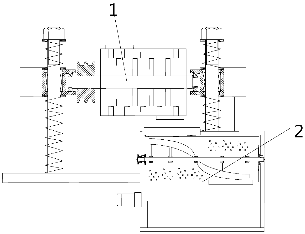
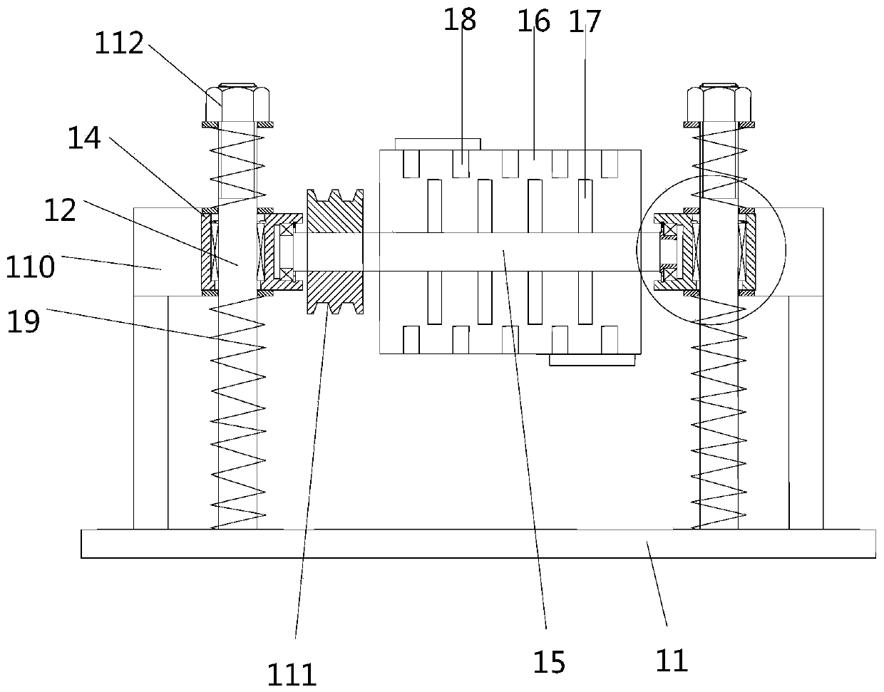
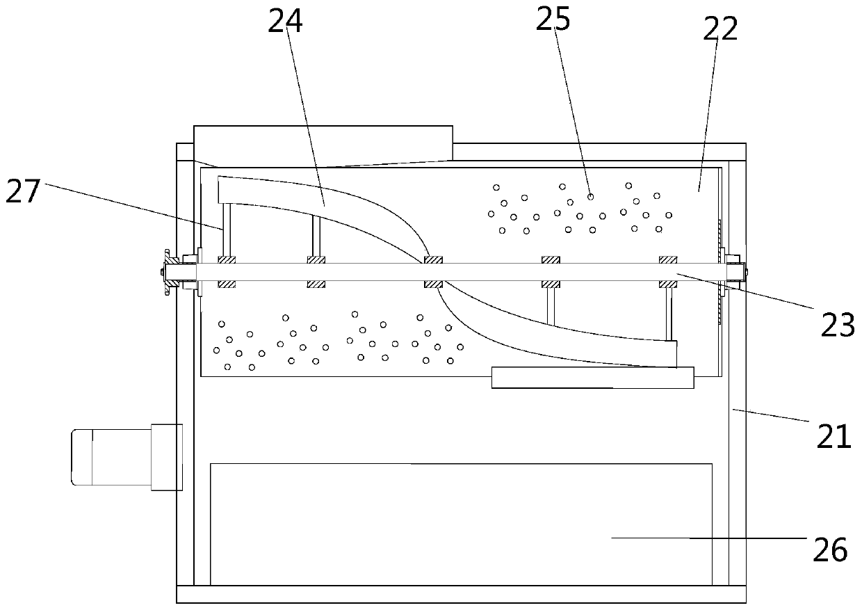
[0017] Embodiment: the drum type deburring device of small parts, structure such as Figure 1 to Figure 5 As shown, a drum deburring mechanism 1 is included, and the discharge port of the drum deburring mechanism 1 is connected with an abrasive separation mechanism 2; There are sliders 14 with built-in sliding sleeves 13 on the top, bearing seats are arranged on the sliders 14, and a rotating shaft 15 is arranged through the bearing seats. A roller 16 fixed to the rotating shaft 15 is arranged on the rotating shaft 15, and is located on the rotating shaft 15 in the roller 16. The first stirring blade 17 is provided, the inner wall of the drum 16 is provided with the second stirring blade 18, the upper and lower sides of the slider 14 are provided with a compression spring 19 sleeved on the column 12, and the slider 14 is also connected with a reciprocating vibration device 110, the rotating shaft 15 on one side of the drum 16 is provided with a transmission device; the abrasiv...


PUM


Abstract

The invention discloses a drum-type deburring device for a small part. The drum-type deburring device comprises a drum deburring mechanism, wherein a discharge port of the drum deburring mechanism isconnected with an abrasive separating mechanism; the drum deburring mechanism comprises a base, a pair of upright posts are arranged on the base, sliding blocks with built-in sliding sleeves are respectively arranged on the pair of upright posts, bearing blocks are arranged on the sliding blocks, a rotating shaft is arranged through the bearing blocks, a drum fixed with the rotating shaft is arranged on the rotating shaft, a first stirring blade is arranged on the rotating shaft positioned in the drum, a second stirring blade is arranged on the inner wall of the drum, compression springs sleeved on the upright posts are arranged on the upper parts and the lower parts of the sliding blocks, reciprocating vibrators are also connected with the sliding blocks, and a transmission device is arranged on the rotating shaft at one side of the drum. The drum-type deburring device for the small part has the advantages of good deburring effect and high working efficiency.

Description

technical field [0001] The invention relates to a deburring device, in particular to a drum type deburring device for small parts. Background technique [0002] The surface deburring of metal parts is an indispensable part of the metal workpiece processing steps. The existing deburring methods include mechanical methods, vibration methods, thermal energy methods, electrochemical methods, etc., and the devices used are also different. The same; among them, the vibration method is designed for small metal parts, especially for the deburring of smaller rotary parts or diamond parts. The parts are put into a large container, which is filled with abrasives, and the fast Reciprocating vibration is used to achieve the purpose of deburring, and can also polish the surface of the part. However, in this deburring method, the parts are easy to deposit on the bottom of the container at the end, and the actual deburring effect is not ideal; and there is no subsequent part and abrasive se...

Claims


Application Information

Patent Timeline
Patent Type & Authority Applications(China)
IPC IPC(8): B24B31/02B24B31/027B24B31/16B24B31/12
CPCB24B31/02B24B31/027B24B31/12B24B31/16
Inventor 钱顺妹
Owner 湖州市漾西电化有限公司
Learn More