A torque feedforward control system and method

A feed-forward control and torque technology, applied in the field of robotics, can solve the problems that the control accuracy of the robot cannot be guaranteed, the tracking accuracy of the robot joint position and the response speed are difficult to be guaranteed, and achieve the effect of improving the dynamic response characteristics and improving the control accuracy

Active Publication Date: 2021-04-06
QUANZHOU HUAZHONG UNIV OF SCI & TECH INST OF MFG +1
View PDF6 Cites 0 Cited by
  • Summary
  • Abstract
  • Description
  • Claims
  • Application Information

AI Technical Summary

Problems solved by technology

[0003] In the traditional robot control strategy, the PID adjustment technology inside the servo drive is used, but the control strategy of the error feedback alone cannot guarantee the control accuracy of the robot during high-speed motion. This strategy ignores all aspects of the robot motion control. Non-linear factors, it is difficult to guarantee the position tracking accuracy and response speed of robot joints under high-speed or heavy-load conditions

Method used


Image

  • A torque feedforward control system and method
  • A torque feedforward control system and method
  • A torque feedforward control system and method

Examples


Embodiment 1

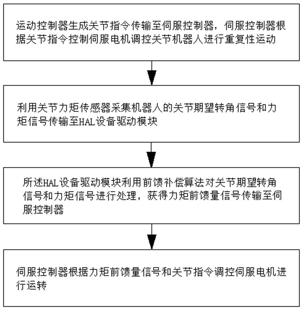
[0044] Such as figure 1 As shown, a torque feedforward control method includes the following steps:

[0045] Step 1. The motion controller 1 generates joint instructions and transmits them to the servo controller 3 through the HAL device driver module 2, and the servo controller 3 controls the servo motor 4 to regulate the joint robot to perform repetitive motion according to the joint instructions;

[0046] Step 2. Utilize the joint torque sensor 5 to collect the joint expected rotation angle signal and torque signal of the robot during the movement, and transmit the collected joint expected rotation angle signal and torque signal to the HAL device driver module 2;

[0047] Step 3. The HAL device driver module 2 uses a feed-forward compensation algorithm to process the joint expected rotation angle signal and torque signal, and obtains a torque feed-forward signal and transmits it to the servo controller 3;

[0048] Step 4. The servo controller 3 controls the servo motor 4 t...

Embodiment 2

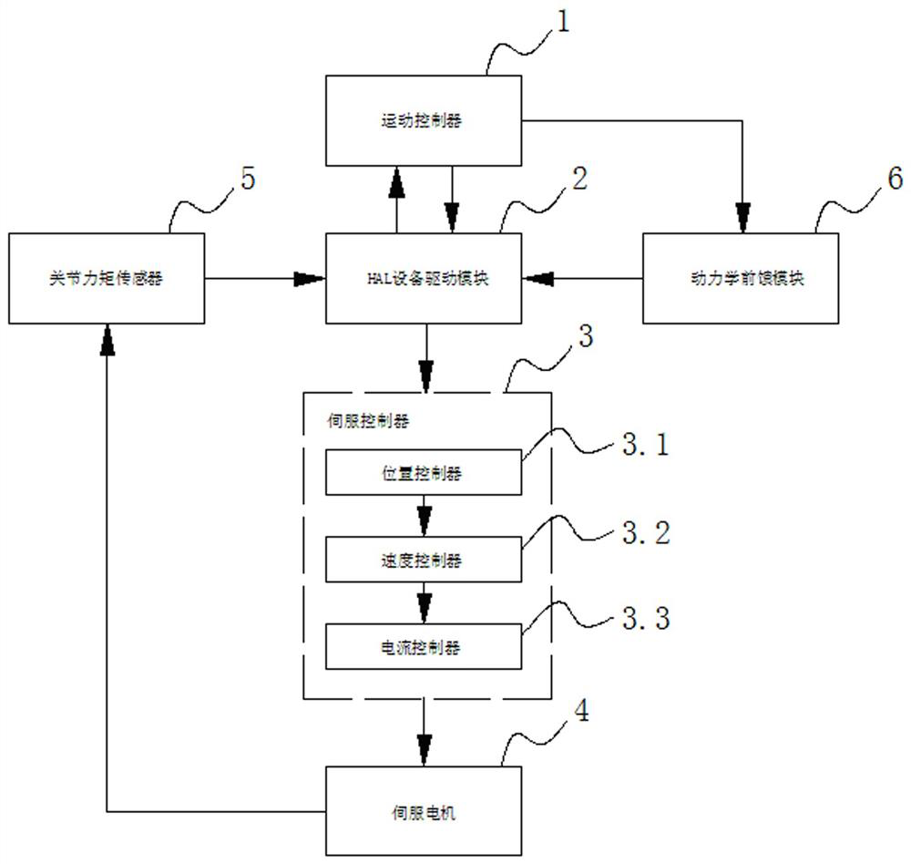
[0073] Such as figure 2 As shown, a torque feedforward control system includes a motion controller 1, a HAL device driver module 2 and a joint torque sensor 5;

[0074] The motion controller 1 is used to generate joint commands, and transmit the joint commands to the HAL device driver module 2;

[0075] The HAL device driver module 2 transmits the joint command to the servo controller 3; it is also used to process the joint expected rotation angle signal and torque signal by using the feedforward compensation algorithm, and obtain the torque feedforward signal and transmit it to the servo controller 3;

[0076] The servo controller 3 is used to control the servo motor 4 to control the joint robot to perform repetitive motion according to the joint command; it is also used to control the servo motor 4 to run according to the torque feedforward signal and the joint command.

[0077] The joint torque sensor 5 is used to collect the joint expected rotation angle signal and torqu...


PUM


Abstract

The present invention relates to a torque feed-forward control system and method. The method includes the following steps: the joint command generated by the motion controller is transmitted to the servo controller through the HAL device drive module, and the servo controller controls the servo motor to regulate the joint robot according to the joint command. Carry out repetitive motion; use the joint torque sensor to collect the joint expected rotation angle signal and torque signal of the robot during the movement, and transmit the collected joint expected rotation angle signal and torque signal to the HAL device driver module; the HAL device driver module uses feedforward compensation The algorithm processes the expected rotation angle signal and torque signal of the joint, obtains the torque feedforward signal and transmits it to the servo controller; the servo controller regulates the servo motor to run according to the torque feedforward signal and joint instructions. Compared with the prior art, the present invention realizes the high-speed movement of the robot, improves the control precision of the robot's trajectory, and improves the dynamic response characteristics of the robot.

Description

technical field [0001] The present invention relates to the technical field of robots, in particular to a torque feedforward control system and method using a joint torque sensor. Background technique [0002] With the continuous maturity of industrial robot technology, the continuous reduction of industrial robot prices and the increase of labor costs, industrial robots are accelerating their integration into all aspects of social production and life, and are playing an increasingly important role. With the advancement of intelligent manufacturing, the advancement of industrial robot technology, industrial development and industry applications have been placed in a prominent position. Industrial robots have been widely used in handling, spraying, welding, assembly and other fields, and are moving towards higher speed and high precision. , The development of high intelligence has put forward more stringent requirements for the control accuracy of robots. [0003] In the tra...

Claims


Application Information

Patent Timeline
Patent Type & Authority Patents(China)
IPC IPC(8): B25J9/16
CPCB25J9/1633
Inventor 张锴焦明杰连志军王平江徐慧陈曼林洪亮
Owner QUANZHOU HUAZHONG UNIV OF SCI & TECH INST OF MFG
Why Eureka
Try Eureka