
Superconducting magnet excitation automatic current lead plugging and unplugging device

A technology of current leads and automatic plugging and unplugging, applied to superconducting magnets/coils, magnetic objects, circuits, etc., can solve problems such as low work efficiency, loss, short circuit, etc., and achieve high safety performance

Pending Publication Date: 2020-03-06
NINGBO JANSEN NMR TECH CO LTD
View PDF0 Cites 0 Cited by
  • Summary
  • Abstract
  • Description
  • Claims
  • Application Information

AI Technical Summary

Problems solved by technology

[0003] In the prior art, superconducting magnets need to be connected with two wires during excitation, usually two guide rods, which are inserted into the low-temperature 4K container from room temperature. During this process, the sealing port of the 4K container will be opened all the time. When helium encounters air, it will condense into ice slag and sink into the 4K container. If the accumulation is small, it will form a layer of condensed frost on the contact point of the electrode, resulting in a short circuit
At the same time, the excitation in the prior art requires manual plugging and unplugging operations. There is no visual observation in the conventional operation, and the whole process is blind operation. Not only is the work efficiency low, but there is also a certain risk of misoperation, and manual operation may cause poor contact or pressure on the electrode contact surface. too big to cause heavy losses

Method used


Image

  • Superconducting magnet excitation automatic current lead plugging and unplugging device
  • Superconducting magnet excitation automatic current lead plugging and unplugging device
  • Superconducting magnet excitation automatic current lead plugging and unplugging device

Examples


Embodiment Construction

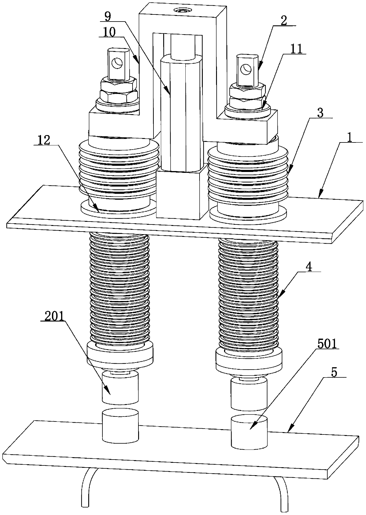
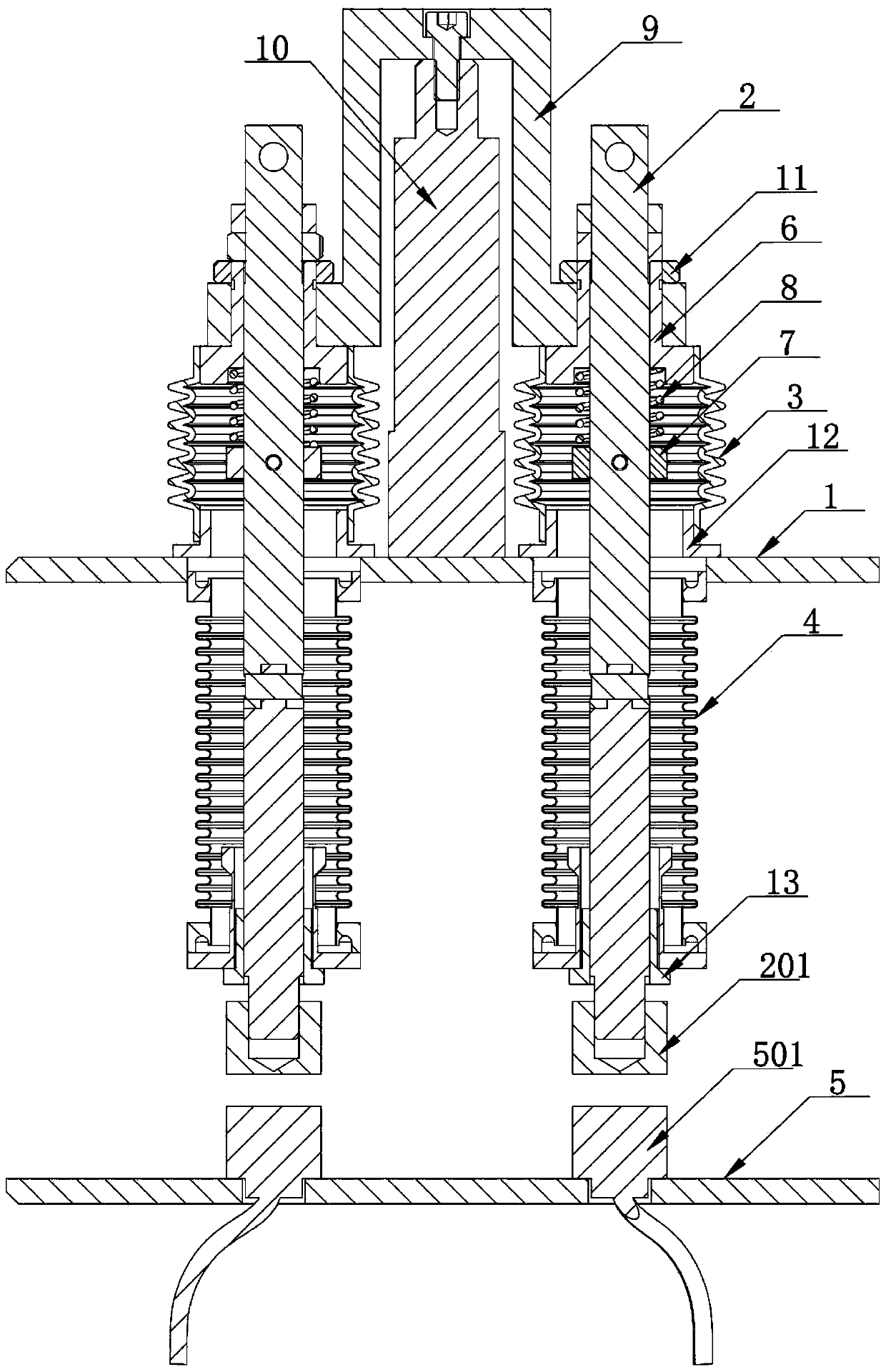
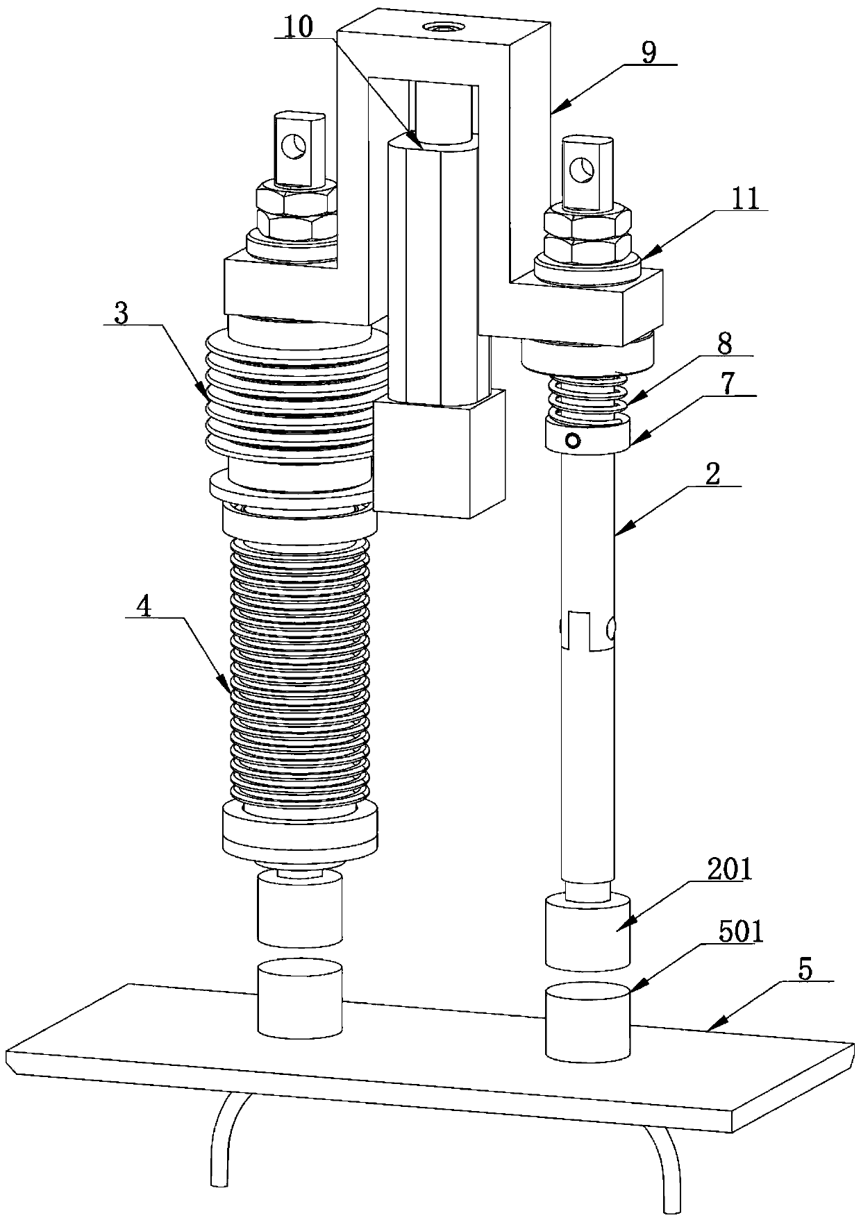
[0021] refer to Figure 1 to Figure 4 , the present invention provides a superconducting magnet excitation automatic plugging and unplugging current lead device, which is installed on an external room temperature container 1, including: a conductive rod 2, a first compression sealing tube 3, a second compression sealing tube 4, a driving device and a synchronization frame 9. A vacuum chamber is set between the room temperature container 1 and the external 4K container 5, and two superconducting coil terminal electrodes 501 are arranged on the 4K container 5, and the two superconducting coil terminal electrodes 501 are located in the vacuum chamber, and the superconducting coil terminal electrodes 501 It is connected with the superconducting coil in the 4K container 5 .

[0022] refer to Figure 2 to Figure 4 , The superconducting magnet excitation automatic plugging and unplugging current lead device is two sets of current lead devices with left and right symmetry, and the t...


PUM


Abstract

The invention provides a superconducting magnet excitation automatic current lead plugging and unplugging device. The device is installed on an external room temperature container and is characterizedby comprising a conducting rod, a first compression sealing pipe and a second compression sealing pipe. A through hole is formed in the room temperature container; the conducting rod penetrates through the through hole; and the upper portion of the conducting rod is sleeved by the first compression sealing pipe; the lower end of the first compression sealing pipe is in sealing connection with thethrough hole, and the upper end of the first compression sealing pipe is connected with the conducting rod and drives the conducting rod to move up and down; the second compression sealing pipe is sleeved at the lower part of the conducting rod; and the upper end of the second compression sealing pipe is hermetically connected with the through hole, and the lower end of the second compression sealing pipe is hermetically connected with the conducting rod. The superconducting magnet excitation automatic current lead plugging and unplugging device can realize automatic plugging and unplugging,and has the advantages of high safety performance, high electrode butt joint precision and stable electrode contact and the like.

Description

technical field [0001] The invention relates to the technical field of superconducting magnets, in particular to a device for automatically plugging and pulling out current leads for superconducting magnet excitation. Background technique [0002] With the development of superconducting magnet technology, the application of superconducting magnets in the medical imaging industry has become very common. The basic principle is to use the superconducting properties of some alloy materials at ultra-low temperatures (generally, the temperature of liquid helium is 4K), place the coils wound with such wires in a closed container, and cool them through cooling and vacuum insulation. And other heat insulation means to create a relatively stable low temperature environment, so that the coil located in it maintains a superconducting state. Wherein, the superconducting coil in the superconducting magnet is conducted with an external circuit through a current lead to generate a magnetic...

Claims


Application Information

Patent Timeline
IPC IPC(8): H01F6/06
CPCH01F6/065
Inventor 黄志龙莫耀敏乐志良郑杰姚海锋徐迅许建益
Owner NINGBO JANSEN NMR TECH CO LTD
Learn More