
Permanent magnet synchronous motor and compressor

A permanent magnet synchronous motor and permanent magnet technology, applied in the field of compressors, can solve the problems of increased torque ripple, large eddy current loss of the motor rotor, and deterioration of the user's sense of hearing, and achieve the effect of increasing the average torque

Pending Publication Date: 2020-03-10
GUANGDONG MEIZHI PRECISION MFG
View PDF0 Cites 0 Cited by
  • Summary
  • Abstract
  • Description
  • Claims
  • Application Information

AI Technical Summary

Problems solved by technology

[0004] (1) There are low-order magnetomotive force harmonics of the armature winding in the gap between the motor stator and the motor rotor. Due to the large penetration depth of such harmonics, large eddy current losses will be generated in the motor rotor, resulting in motor performance deterioration
[0005] (2) The low-order harmonics of the armature magnetic field will also make the internal magnetic field distribution of the motor uneven, resulting in local saturation of the motor, thereby reducing the average torque of the motor and increasing the torque ripple, resulting in greater vibration Noise, worsening the user's sense of hearing

Method used


Image

  • Permanent magnet synchronous motor and compressor
  • Permanent magnet synchronous motor and compressor
  • Permanent magnet synchronous motor and compressor

Examples


Embodiment Construction

[0052] In order to understand the above-mentioned purpose, features and advantages of the present invention more clearly, the present invention will be further described in detail below in conjunction with the accompanying drawings and specific embodiments. It should be noted that, in the case of no conflict, the embodiments of the present application and the features in the embodiments can be combined with each other.

[0053] In the following description, many specific details are set forth in order to fully understand the present invention. However, the present invention can also be implemented in other ways different from those described here. Therefore, the protection scope of the present invention is not limited by the specific details disclosed below. EXAMPLE LIMITATIONS.

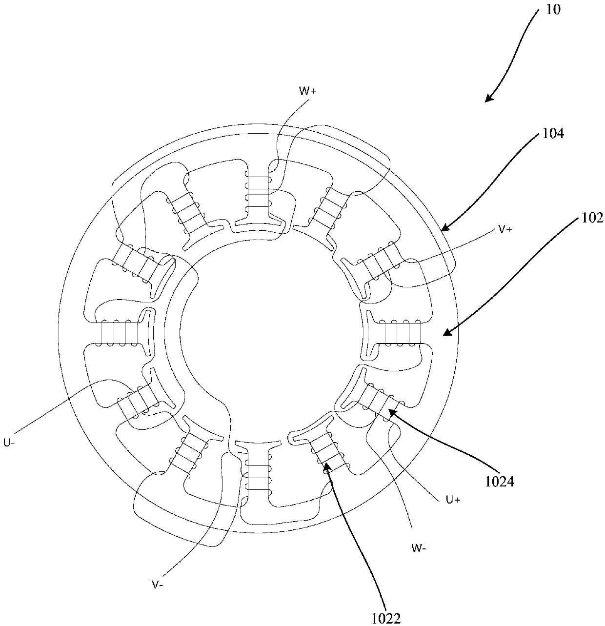
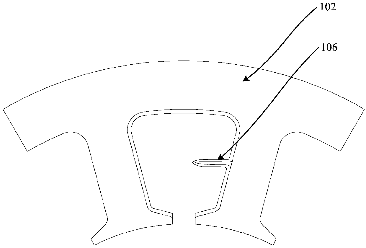
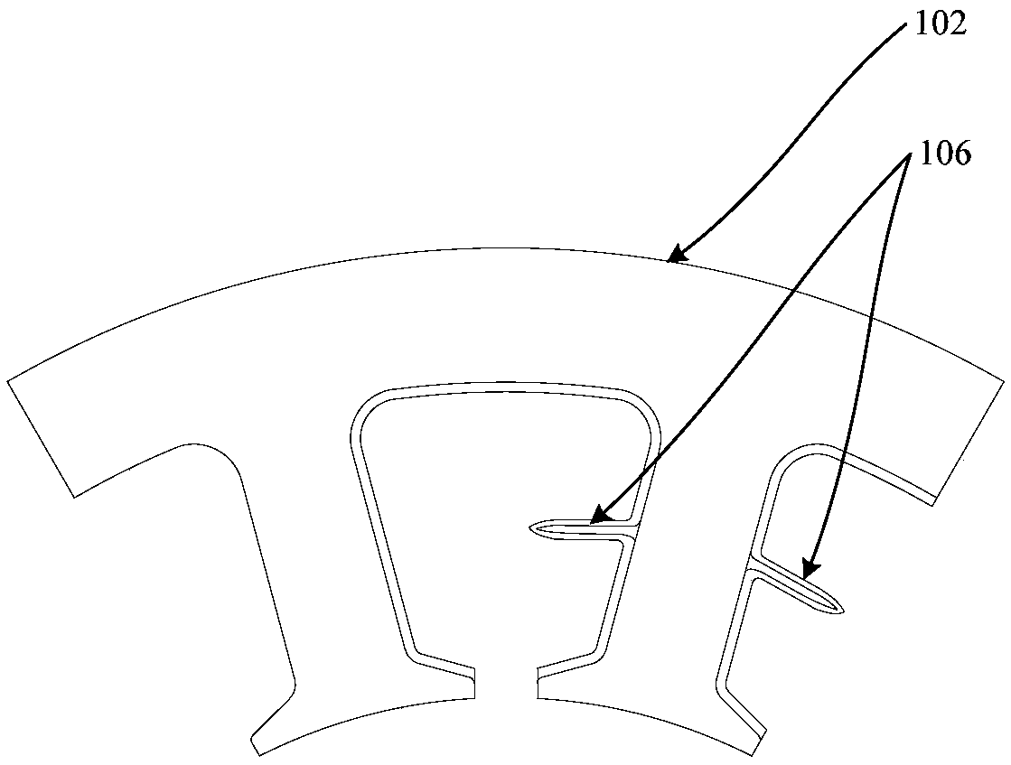
[0054] Refer below Figure 1 to Figure 3 A permanent magnet synchronous machine according to some embodiments of the invention is described.

[0055] Such as Figure 1 to Figure 3 As shown, the pe...


PUM


Abstract

The invention provides a permanent magnet synchronous motor and a compressor. The permanent magnet synchronous motor comprises a motor stator and a motor rotor, wherein the motor stator comprises a stator core and a stator winding, the stator core comprises a plurality of stator teeth in the circumferential direction, a stator slot is defined between any two adjacent stator teeth, and the stator slots are used for accommodating the stator winding wound on the stator teeth; the motor rotor is sleeved and matched with the motor stator, the motor rotor comprises a rotor core and a plurality of permanent magnets, the end face of the rotor core is provided with a plurality of groups of slots in the circumferential direction of the rotor core, the plurality of permanent magnets are embedded in the plurality of groups of accommodating slots, the plurality of stator teeth can be divided into a plurality of tooth groups which are sequentially arranged according to the rotation direction of themotor rotor, each tooth group comprises a plurality of stator teeth which are adjacent in pairs, and at least one stator tooth in the plurality of stator teeth which are adjacent in pairs is wound with an out-phase winding. According to the technical scheme of the invention, the counter electromotive force of the stator winding can be improved when the motor is in operation, so that the copper loss of the winding is reduced, and the motor performance is improved.

Description

technical field [0001] The invention relates to the field of compressors, in particular to a permanent magnet synchronous motor and a compressor. Background technique [0002] The permanent magnet synchronous motor in the rotary DC inverter compressor mostly adopts a permanent magnet motor with a built-in permanent magnet structure, and each coil of the stator winding is wound on the stator teeth. [0003] In the related art, the number of poles of the magnet in the rotor core and the number of stator slots on the motor stator are 5:6 or 7:6, so that the permanent magnet synchronous motor has a higher winding coefficient, and then can Improve the efficiency of the motor, but the permanent magnet of this structure has the following defects: [0004] (1) There are low-order magnetomotive force harmonics of the armature winding in the gap between the motor stator and the motor rotor. Due to the large penetration depth of such harmonics, large eddy current losses will be genera...

Claims


Application Information

Patent Timeline
Patent Type & Authority Applications(China)
IPC IPC(8): H02K1/16H02K3/28H02K3/16
CPCH02K1/165H02K3/16H02K3/28
Inventor 徐飞邱小华乔正忠毛临书王玉龙
Owner GUANGDONG MEIZHI PRECISION MFG
Learn More