Pre-tensioning device and pre-tensioning method for steel belts
A steel belt and plug-in technology, which is applied in the field of robots, can solve the problems of large volume, unsuitable multi-layer steel belt pretensioning, and uncompact structure of the robot steel belt pretensioning device, so as to achieve the overall small size, compact structure, and occupation small size effect
- Summary
- Abstract
- Description
- Claims
- Application Information
AI Technical Summary
Problems solved by technology
Method used
Image
Examples
specific Embodiment approach 1
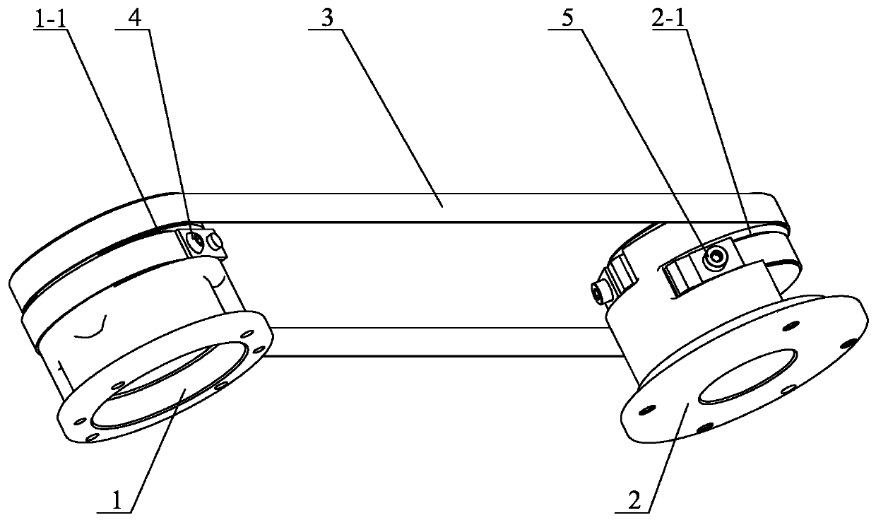
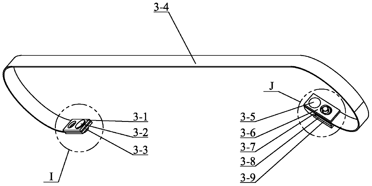
[0022] Specific embodiment one: combination Figure 1 to Figure 5 To illustrate this embodiment, a steel belt pretensioning device described in this embodiment includes a steel belt wheel A1, a steel belt wheel B2, a steel belt assembly 3, a first fastening bolt 4 and a second fastening bolt 5, and the steel belt assembly One end of 3 is fixed to the outer circumferential side wall of the steel belt pulley A1 through the first fastening bolt 4, and the other end of the steel belt assembly 3 is fixed to the outer circumferential side wall of the steel belt wheel B2 through the second fastening bolt 5 on;
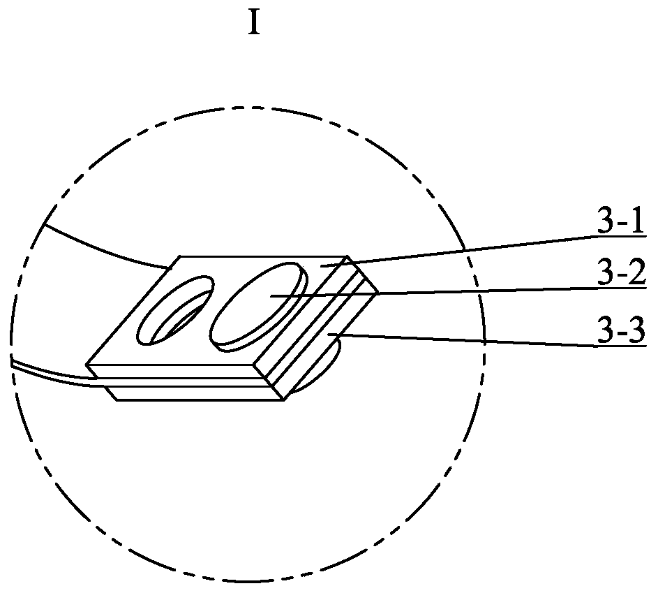
[0023] The steel belt assembly 3 includes a first pressure plate 3-1, a first cylindrical pin 3-2, a second pressure plate 3-3, a second cylindrical pin 3-5, a third pressure plate 3-6, a wedge-shaped pressure plate 3-7, and a fourth The pressure plate 3-9, one end of the steel belt 3-4 is fixedly connected between the first pressure plate 3-1 and the second pressure plate 3-3,...
specific Embodiment approach 2
[0024] Specific implementation manner two: combination Figure 1 to Figure 5 To explain this embodiment, the outer end surface of the fourth pressing plate 3-9 and the wall of the wedge groove 3-7-1 is an inclined surface, and the inclination direction of the inclined surface is the same as that of the groove wall of the wedge groove 3-7-1. Consistent. The technical features not disclosed in this embodiment are the same as those in the first embodiment.
[0025] In this design, the inclined surface of the fourth pressure plate 3-9 is matched with the groove wall of the wedge groove 3-7-1 to prevent the stress concentration phenomenon of the fourth pressure plate 3-9.
specific Embodiment approach 3
[0026] Specific implementation mode three: combination figure 1 To illustrate this embodiment, the outer circumferential side wall of the steel pulley A1 described in this embodiment is provided with a groove A1-1 along the circumferential direction, one end of the steel belt assembly 3 is clamped in the groove A1-1, and the steel pulley The outer circumferential side wall of B2 is provided with a groove B2-1 along the circumferential direction, and the other end of the steel belt assembly 3 is clamped in the groove B2-1. The technical features not disclosed in this embodiment are the same as those in the first or second embodiment.
[0027] This design is so as to realize the axial positioning between the steel belt assembly 3 and the steel belt wheel A1 and the steel belt wheel B2.
PUM
 Abstract
Description
Claims
Application Information
 - R&D
- Intellectual Property
- Life Sciences
- Materials
- Tech Scout
- Unparalleled Data Quality
- Higher Quality Content
- 60% Fewer Hallucinations
Browse by: Latest US Patents, China's latest patents, Technical Efficacy Thesaurus, Application Domain, Technology Topic, Popular Technical Reports.
© 2025 PatSnap. All rights reserved.Legal|Privacy policy|Modern Slavery Act Transparency Statement|Sitemap|About US| Contact US: help@patsnap.com


