RFID tag antenna, RFID tag, and cable joint

A technology of RFID tags and antennas, applied in the field of radio frequency identification, can solve problems such as difficult reading of temperature data, achieve the effects of reducing manufacturing costs, increasing energy, simplifying structure and manufacturing processes

Pending Publication Date: 2020-03-13
ZHEJIANG JOHAR TECH CO LTD
View PDF0 Cites 0 Cited by
  • Summary
  • Abstract
  • Description
  • Claims
  • Application Information

AI Technical Summary

Problems solved by technology

However, in the power ring network cabinet, the reader corresponding to the RFID tag can only be installed on the top of the power ring network cabinet, and the reading direction of the reader is perpendicular to the maximum gain direction of the anti-metal tag
Therefore, although the anti-metal tag solves the influence of metal structural parts and greatly improves the gain, it is difficult for the reader to read the temperature data detected by the RFID tag due to the limitation of the installation position of the reader.

Method used


Image

  • RFID tag antenna, RFID tag, and cable joint
  • RFID tag antenna, RFID tag, and cable joint
  • RFID tag antenna, RFID tag, and cable joint

Examples


Embodiment Construction

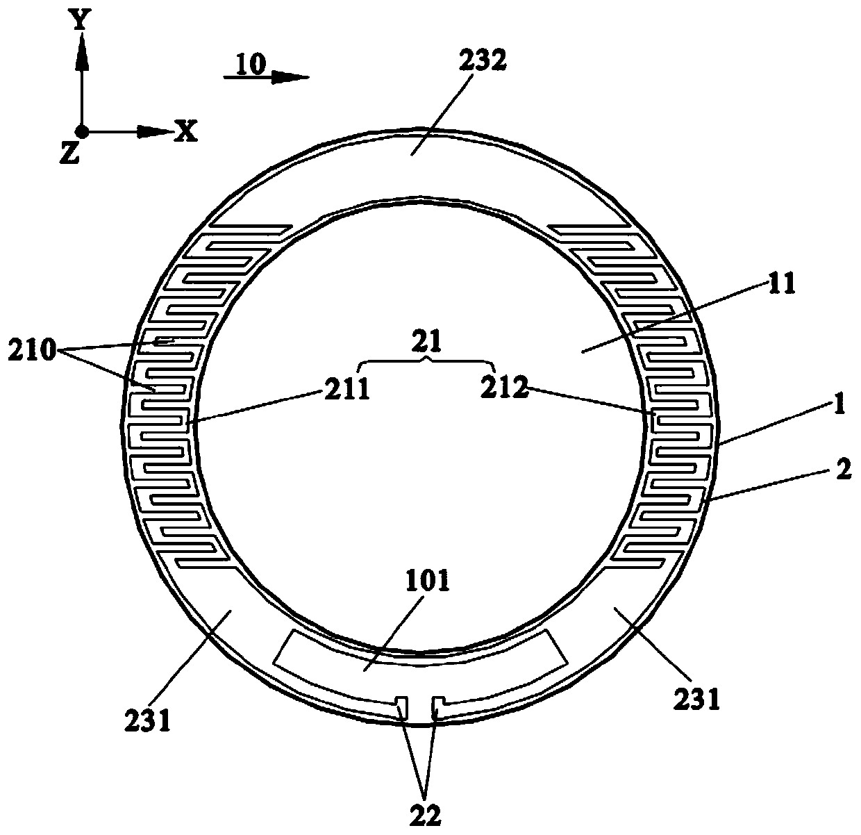
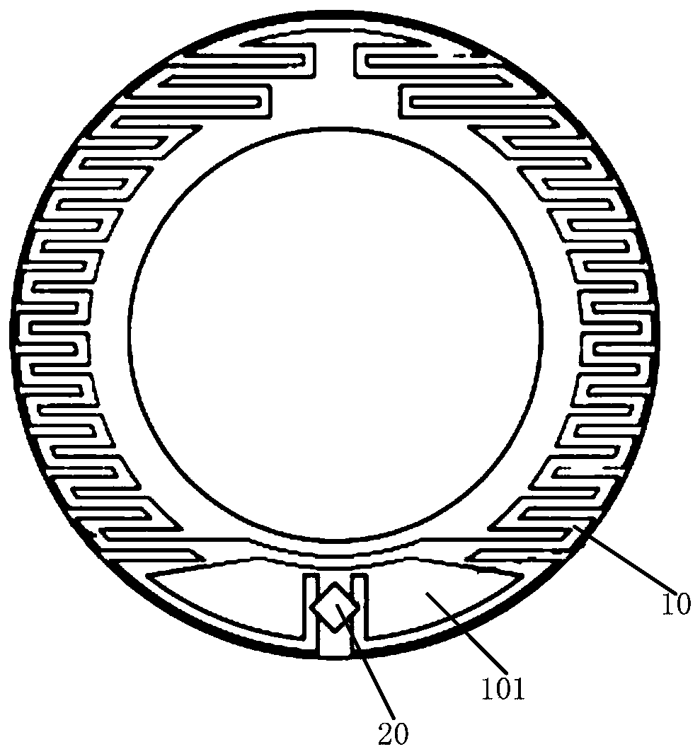
[0024] Such as figure 1 As shown, the RFID tag antenna 10 provided in this embodiment includes a substrate 1 and an antenna structure 2 . The center of the base plate 1 has a through hole 11, and the cross section of the base plate 1 is generally circular or elliptical. The antenna structure 2 includes a radiation part 21 and a feeding part 22 . The radiation portion 21 is disposed on the surface of the substrate 1 and is continuously distributed along the circumference of the substrate 1 . The radiation portion 21 has at least one groove 210 opening toward the inside or outside of the substrate. The power feeding part 22 is electrically connected to the radiation part 21 , and the power feeding part 22 and the radiation part 21 form an impedance adjustment region 101 on the substrate 1 .

[0025] In this embodiment, if figure 1 As shown, the cross section of the substrate 1 is circular. However, the present invention does not make any limitation thereto. In other embodim...


PUM


Abstract

The invention provides an RFID tag antenna, an RFID tag and a cable joint. The RFID tag antenna comprises a substrate and an antenna structure. A through hole is formed in the center of the substrate,and a basic cross section is in a circular ring shape or an oval ring shape. An antenna structure comprises a radiation part and a feed part. Radiation parts are arranged on the surface of the substrate and continuously distributed in the circumferential direction of the substrate, and each radiation part is provided with at least one groove with an opening facing the inner side or the outer sideof the substrate. The feed portion is electrically connected to the radiation portion, and the feed portion and the radiation portion form an impedance adjustment region on the substrate.

Description

technical field [0001] The invention relates to the technical field of radio frequency identification, and in particular to an RFID tag antenna, an RFID tag and a cable joint. Background technique [0002] In the power ring network cabinet, the working voltage is often above 10KV, and the key nodes in the cable are often accompanied by high temperature and heat, and these nodes are often important hidden dangers of power accidents. The key nodes in the power cabinet are often located at the T-shaped cable joints. The T-shaped cable joints are used in the main network system of the cable distribution box or as the incoming and outgoing cable joints of the ring network cabinet. Combination sockets can also be combined with bus bushings above 600A and rear T-shaped cable joints to form multi-channel cable branches. T-type cable connectors are generally divided into front and rear plugs, and are equipped with insulating plugs to achieve the functions of insulation, sealing and ...

Claims


Application Information

Patent Timeline
Patent Type & Authority Applications(China)
IPC IPC(8): H01Q1/22H01Q1/36H01Q1/38H01Q1/50
CPCH01Q1/2225H01Q1/36H01Q1/38H01Q1/50
Inventor 刘健朱红锋林生洲祝祺斌季宏红
Owner ZHEJIANG JOHAR TECH CO LTD
Why Eureka
Try Eureka