
An intermittent cyclone separation device

A cyclone separation device and intermittent technology, which are applied in separation methods, liquid separation, chemical instruments and methods, etc., can solve the problems of small oil core diameter and reduce cyclone separation efficiency, etc., and achieve low cost, improved efficiency, and structure simple effect

Active Publication Date: 2021-06-11
NORTHEAST GASOLINEEUM UNIV
View PDF0 Cites 0 Cited by
  • Summary
  • Abstract
  • Description
  • Claims
  • Application Information

AI Technical Summary

Problems solved by technology

However, in this process, the oil nuclei in the central area are dynamically formed and continuously discharged, which will largely cause the diameter of the oil nuclei to be small, so that the inside of the oil phase outlet pipe is divided between the oil nuclei and the oil phase. There is more water phase in the annular area formed between the inner walls of the outlet pipe, which will inevitably cause the oil nucleus to flow out with the surrounding water phase, which greatly reduces the efficiency of cyclone separation

Method used


Image

  • An intermittent cyclone separation device
  • An intermittent cyclone separation device
  • An intermittent cyclone separation device

Examples


Embodiment Construction

[0032] The present invention will be further described below in conjunction with accompanying drawing:

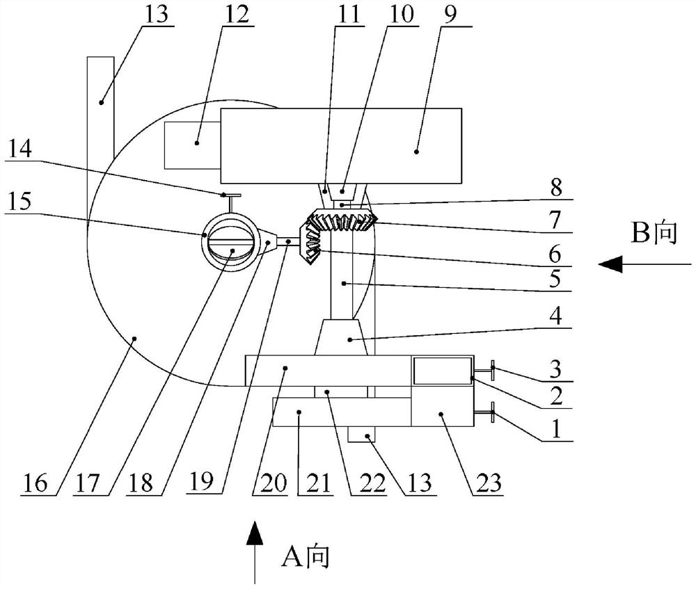
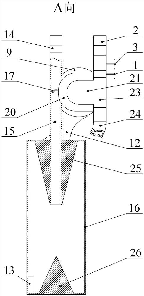
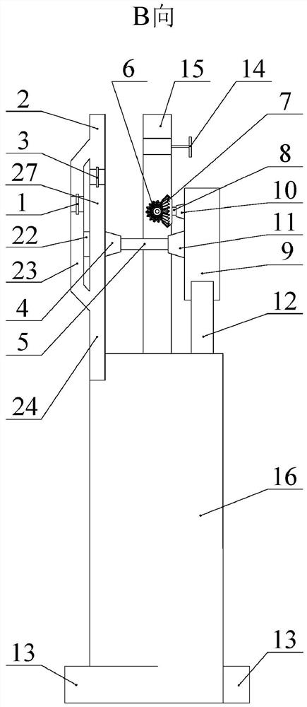
[0033] Such as Figure 1 to Figure 13 As shown, a high-efficiency gap type cyclone separation device according to the embodiment of the present invention includes a bypass pipe valve 1, an aqueous phase outlet pipe 2, a rotational speed regulating pipe valve 3, an impeller sealing structure 4, an impeller shaft 5, and a small bevel gear 6 , large bevel gear 7, large bevel gear shaft 8, intermittent rotation mechanism housing 9, large bevel gear shaft sealing structure 10, intermittent mechanism sealing structure 11, fixed structure 12, tangential inlet 13, oil phase outlet pipe valve 14, oil Phase outlet pipe 15, swirl chamber 16, oil phase baffle 17, small bevel gear shaft sealing structure 18, small bevel gear shaft 19, impeller housing 20, cam chamber 21, shaft sleeve 22, bypass pipe 23, cutting To the outlet 24, the outlet cone 25, the inlet cone 26, the rotating speed...


PUM


Abstract

An intermittent cyclone separation device. Including water phase outlet pipe, impeller shaft, small bevel gear, large bevel gear, large bevel gear shaft, intermittent rotation mechanism shell, large bevel gear shaft sealing structure, fixed structure, tangential inlet, oil phase outlet pipe, swirl chamber , oil phase baffle, small bevel gear shaft, impeller housing, bypass pipe, tangential outlet, outlet cone, inlet cone, speed regulating pipe, impeller, rotating disc, guide groove, push block, guide column and cross block, etc. . The tangential outlet is an arc structure, the tangential outlet is tangent to the top of the swirl chamber at the end close to the swirl chamber, and the tangential outlet is bifurcated at the end far away from the swirl chamber to form a bypass pipe and a speed regulating pipe. The impeller housing is located on the rotating speed regulating pipe; the impeller is located in the chamber formed by the impeller housing and the rotating speed regulating pipe; the large bevel gear is located outside the intermittent rotating mechanism housing. The invention has the advantages of high separation efficiency, strong system integration, compact structure and low cost.

Description

technical field [0001] The invention relates to a cyclone separation device applied in the fields of petroleum, chemical industry, environmental protection and the like, which is aimed at separating two-phase immiscible media with density differences. Background technique [0002] Compared with other types of separation methods, hydrocyclones that use centrifugal separation methods for separation of immiscible media have the advantages of compact structure and rapid separation. At present, hydrocyclones have been widely used in the fields of petroleum exploration, chemical industry and municipal environmental protection. The separation principle of the hydrocyclone is to use the density difference between immiscible media for centrifugal separation, and its separation efficiency is directly affected by the density difference of the multiphase medium to be separated and the particle size of the dispersed phase and other physical parameters. However, in the field of oilfield ...

Claims


Application Information

Patent Timeline
Patent Type & Authority Patents(China)
IPC IPC(8): B01D17/038
CPCB01D17/0217
Inventor 宋民航赵姝婷杨宏燕刘琳张爽邢雷
Owner NORTHEAST GASOLINEEUM UNIV
Learn More